
Chapter 12
Fundamentals of Electricity & Electronics
a DC generator, since it is used in DC systems. Although its output is a DC voltage, it is an alternator rectifier unit. This type of alternator rectifier is a self-excited unit but does not contain a permanent magnet. The excitation for starting is obtained from the battery; immediately after starting, the unit is self-exciting. Cooling air for the alternator is conducted into the unit by a blast air tube on the air inlet cover.
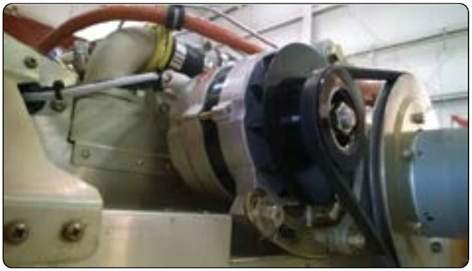
The alternator is directly coupled to the aircraft engine by means of a flexible drive coupling. The output of the alternator portion of the unit is three-phase alternating current, derived from a three-phase, delta connected system incorporating a three-phase, full-wave bridge rectifier. [Figure 12-323] This unit operates in a speed range from 2,100 to 9,000 rpm, with a DC output voltage of 26–29 volts and 125 amperes.
Brushless Alternator
This design is more efficient because there are no brushes to wear down or to arc at high altitudes. This generator consists of a pilot exciter, an exciter, and the main generator system. The need for brushes is eliminated by using an integral exciter with a rotating armature that has its AC output rectified for the main AC field, which is also of the rotating type. [Figure 12-324]
The pilot exciter is an 8-pole, 8,000 rpm, 533 cps, AC generator. The pilot exciter field is mounted on the main generator rotor shaft and is connected in series with the main generator field. The pilot exciter armature is mounted on the main generator stator. The AC output of the pilot exciter is supplied to the voltage regulator, where it is rectified and controlled, and is then impressed on the exciter field winding to furnish excitation for the generator.
The exciter is a small AC generator with its field mounted on the main generator stator and its three-phase armature mounted on the generator rotor shaft. Included in the exciter field are permanent magnets mounted on the main generator stator between the exciter poles.
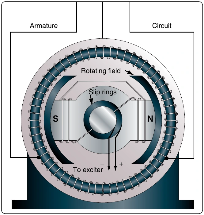
The exciter field resistance is temperature compensated by a thermistor. This aids regulation by keeping a nearly constant resistance at the regulator output terminals. The exciter output is rectified and impressed on the main generator field and the pilot exciter field. The exciter stator has a stabilizing field, which is used to improve stability and to prevent voltage regulator over-corrections for changes in generator output voltage.
The AC generator shown in Figure 12-324 is a 6-pole, 8,000 rpm unit having a rating of 31.5 kilovoltamperes (kVA), 115⁄200 volts, 400 cps. This generator is three-phase, 4 wire, wye connected with grounded neutrals. By using an integral AC exciter, the necessity for brushes within the generator has been eliminated. The AC output of the rotating exciter armature is fed directly into the three-phase, full-wave, rectifier bridge located inside the rotor shaft, which uses high-temperature silicon rectifiers. The DC output from the rectifier bridge is fed to the main AC generator rotating field.
Voltage regulation is accomplished by varying the strength of the AC exciter stationary fields. Polarity reversals of the AC generator are eliminated and radio noise is minimized by the absence of the brushes. A noise filter mounted on the alternator further reduces any existing radio noise. The rotating pole structure of the generator is laminated from steel punchings, containing all six poles and a connecting hub section. This provides optimum magnetic and mechanical properties.
Some alternators are cooled by circulating oil through steel tubes. The oil used for cooling is supplied from the constant speed drive assembly. Ports located in the flange connecting the generator and drive assemblies make oil flow between the constant speed drive and the generator possible.
Voltage is built up by using permanent magnet interpoles in the exciter stator. The permanent magnets assure a voltage buildup, precluding the necessity of field flashing. The rotor of the alternator may be removed without causing loss of the alternator’s residual magnetism.
Alternator Frequency
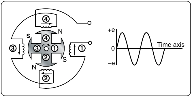
The frequency of the alternator voltage depends upon the speed of rotation of the rotor and the number of poles. The faster the speed, the higher the frequency; the lower the speed, the lower the frequency. The more poles on the rotor, the higher the frequency for a given speed. When a rotor has rotated through an angle so that two adjacent rotor poles (a North and a South pole) have passed one winding, the voltage induced in that winding has varied through one complete cycle. For a given frequency, the greater the number of pairs of poles, the lower the speed of rotation. A two-pole alternator rotates at twice the speed of a four-pole alternator for the same frequency of generated voltage. The frequency of the alternator in cycles per minute (cpm) is related to the number of poles and the speed, as expressed by the equation:
Where: P is the number of poles per phase f is the frequency in cps N is the rated speed in rpm
For example, a 2-pole, 3,600 rpm alternator has a frequency of: