Chapter 12
Fundamentals of Electricity & Electronics
To design a series motor for satisfactory operation on AC, the following changes are made:
- The eddy current losses are reduced by laminating the field poles, frame, and armature.
- Hysteresis losses are minimized by using high permeability, transformer-type, silicon steel laminations.
- The reactance of the field windings is kept satisfactorily low by using shallow pole pieces, few turns of wire, low frequency (usually 25 cycles for large motors), low flux density, and low reluctance (a short air gap).
- The reactance of the armature is reduced by using a compensating winding embedded in the pole pieces. If the compensating winding is connected in series with the armature, as shown in Figure 12-314, the armature is conductively compensated. If the compensating winding is designed as shown in Figure 12-315, the armature is inductively compensated. If the motor is designed for operation on both DC and AC circuits, the compensating winding is connected in series with the armature. The axis of the compensating winding is displaced from the main field axis by an angle of 90°. This arrangement is similar to the compensating winding used in some DC motors and generators to overcome armature reaction. The compensating winding establishes a counter magnetomotive force, neutralizing the effect of the armature magnetomotive force, preventing distortion of the main field flux, and reducing the armature reactance. The inductively compensated armature acts like the primary of a transformer, the secondary
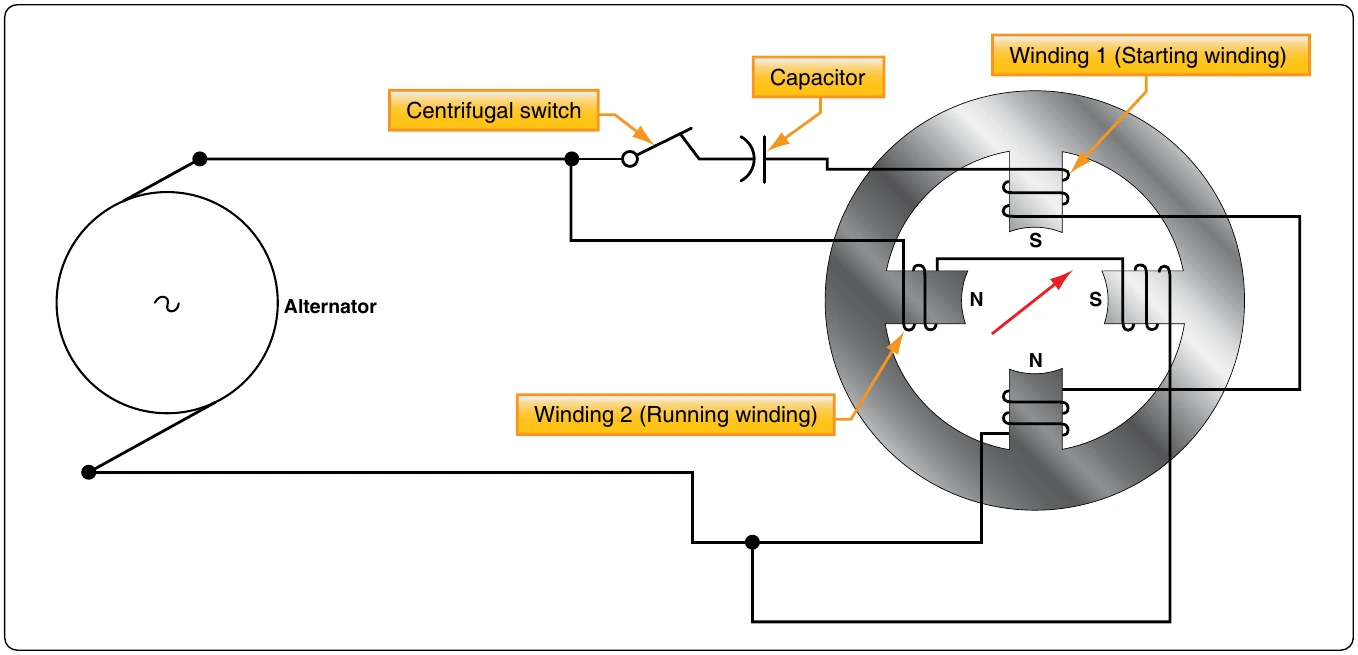
current flowing through the turns of the compensating winding establishes the opposing magnetomotive force, neutralizing the armature reactance.
- Sparking at the commutator is reduced by the use of preventive leads P1, P2, P3, and so forth, as shown in Figure 12-316, where a ring armature is shown for simplicity. When coils at A and B are shorted by the brushes, the induced current is limited by the relatively high resistance of the leads. Sparking at the brushes is also reduced by using armature coils having only a single turn and multipolar fields. High torque is obtained by having a large number of armature conductors and a large diameter armature. Thus, the commutator has a large number of very thin commutator bars and the armature voltage is limited to about 250 volts.
Fractional horsepower AC series motors are called universal motors. They do not have compensating windings or preventive leads. They are used extensively to operate fans and portable tools, such as drills, grinders, and saws.
Maintenance of AC Motors
The inspection and maintenance of AC motors is very simple. The bearings may or may not need frequent lubrication. If they are the sealed type, lubricated at the factory, they require no further attention. Be sure the coils are kept dry and free from oil or other abuse. The temperature of a motor is usually its only limiting operating factor. A good rule of thumb is that a temperature too hot for the hand is too high for safety. Next to the temperature, the sound of a motor or generator is the best trouble indicator. When operating properly, it should hum evenly. If it is overloaded it “grunts.” A three-phase motor with one lead disconnected refuses to turn and “growls.” A knocking sound generally indicates a loose armature coil, a shaft out of alignment, or armature dragging because of worn bearings. In all cases, the inspection and maintenance of all AC motors should be performed in accordance with the applicable manufacturer’s instructions.
Alternators
Basic Alternators & Classifications
An electrical generator is a machine that converts mechanical energy into electrical energy by electromagnetic induction. A generator that produces alternating current is referred to as an AC generator and, through combination of the words “alternating” and “generator,” the word “alternator” has come into widespread use. In some areas, the word “alternator” is applied only to small AC generators. This handbook treats the two terms synonymously and uses the term “alternator” to distinguish between AC and DC generators.
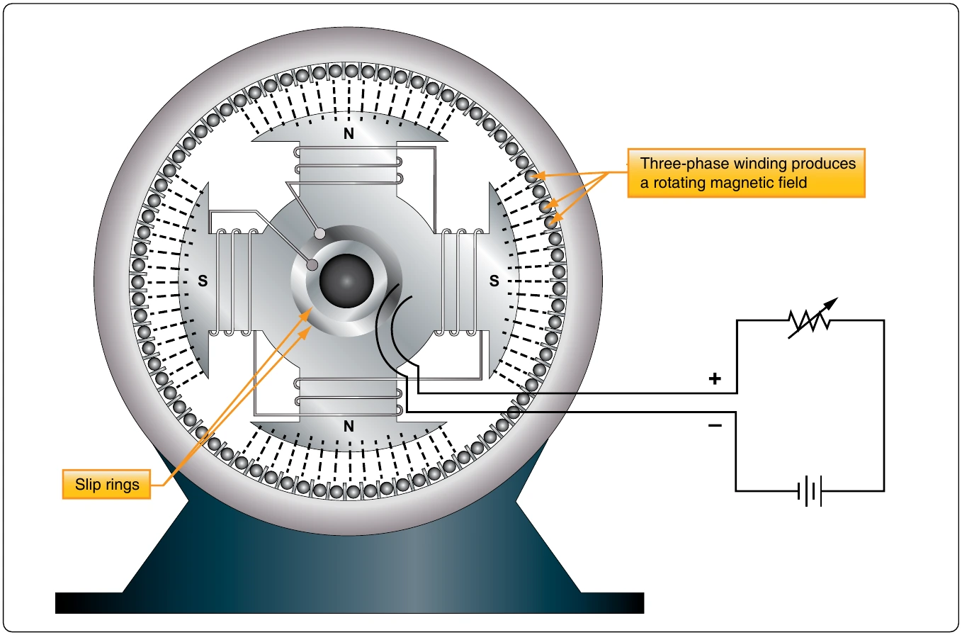
The major difference between an alternator [Figure 12-317] and a DC generator is the method of connection to the external circuit. The alternator is connected to the external circuit by slip rings, but the DC generator is connected by a commutator.
Method of Excitation
One means of classification is by the type of excitation system used. In alternators used on aircraft, excitation can be affected by one of the following methods:
- A direct connected, DC generator. This system consists of a DC generator fixed on the same shaft with the AC generator. A variation of this system is a type of alternator that uses DC from the battery for excitation, after which the alternator is self-excited.
- By transformation and rectification from the AC system. This method depends on residual magnetism for initial AC voltage buildup, after which the field is supplied with rectified voltage from the AC generator.
- Integrated brushless type. This arrangement has a DC generator on the same shaft with an AC generator. The excitation circuit is completed through silicon rectifiers rather than a commutator and brushes. The rectifiers are mounted on the generator shaft and their output is fed directly to the AC generator’s main rotating field.
Number of Phases
Another method of classification is by the number of phases of output voltage. AC generators may be single-phase, two-phase, three-phase, or even six-phase and more. In the electrical systems of aircraft, the three-phase alternator is by far the most common.