
Chapter 5
Physics for Aviation
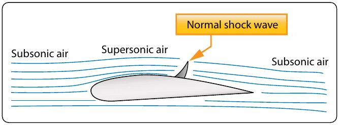
If an airplane designed to fly subsonic, perhaps at a Mach number of 0.80, flies too fast and enters transonic flight, some noticeable changes will take place with respect to the airflow over the wing. Figure 5-79 shows six views of a wing, with each view showing the Mach number getting higher.
The scenario for the six views is as follows:
- The Mach number is fairly low, and the entire wing is experiencing subsonic airflow.
- The velocity has reached the critical Mach number, where the airflow over the top of the wing is reaching
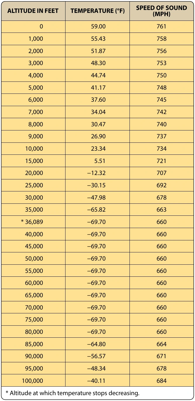
and a normal shock wave has formed on the top of the wing. Some airflow separation starts to occur behind the shock wave.
- The velocity has continued to increase beyond the critical Mach number, and the normal shock wave has moved far enough aft that serious airflow separation is occurring. A normal shock wave is now forming on the bottom of the wing as well. Behind the normal
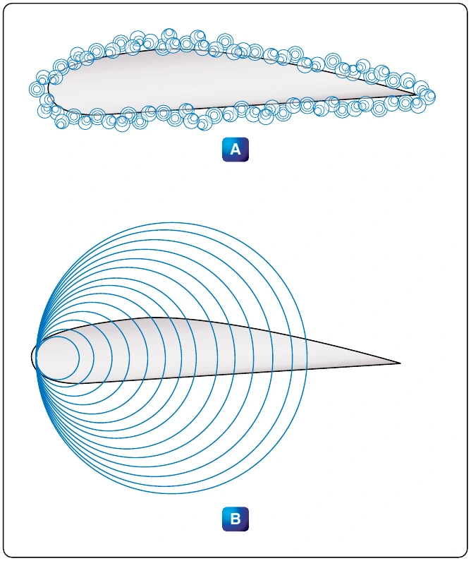
- The velocity has increased to the point that both shock waves on the wing, top and bottom, have moved to the back of the wing and attached to the trailing edge. Some airflow separation is still occurring.
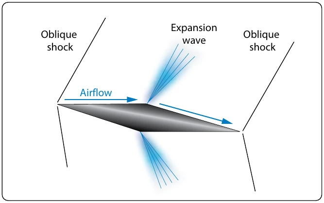
- The forward velocity of the airfoil is greater than Mach 1, and a new shock wave has formed just forward of the leading edge of the wing. If the wing has a sharp leading edge, the shock wave will attach itself to the sharp edge.
The airfoil shown in Figure 5-79 is not properly designed to handle supersonic airflow. The bow wave in front of the wing leading edge of view F would be attached to the leading edge, if the wing was a double wedge or biconvex design. These two wing designs are shown in Figure 5-80.
Aerodynamic Heating
One of the problems with airplanes and high-speed flight is the heat that builds up on the airplane’s surface because of air friction. When the SR-71 Blackbird airplane is cruising at Mach 3.5, skin temperatures on its surface range from 450 °F to over 1,000 °F. To withstand this high temperature, the airplane was constructed of titanium alloy, instead of the traditional aluminum alloy. The supersonic transport Concorde was originally designed to cruise at Mach 2.2, but its cruise speed was reduced to Mach 2.0 because of structural problems that started to occur because of aerodynamic heating. If airplanes capable of hypersonic flight are going to be built in the future, one of the obstacles that will have to be overcome is the stress on the airplane’s structure caused by heat.
Helicopter Aerodynamics
The helicopter, as we know it today, falls under the classification known as rotorcraft. Rotorcraft is also known as rotary wing aircraft, because instead of their wing being fixed like it is on an airplane, the wing rotates. The rotating wing of a rotorcraft can be thought of as a lift producing device, like the wing of an airplane, or as a thrust producing device, like the propeller on a piston engine.
Helicopter Structures and Airfoils
The main parts that make up a helicopter are the cabin, landing gear, tail boom, power plant, transmission, main rotor, and tail rotor. [Figure 5-81]
Main Rotor Systems
In the fully articulated rotor system, the blades are attached to the hub multiple times. The blades are hinged in a way that allows them to move up and down and fore and aft, and bearings provide for motion around the pitch change axis. Rotor systems using this type of arrangement typically have three or more blades. The hinge that allows the blades to move up and down is called the flap hinge, and movement around this hinge is called flap. The hinge that allows the blades to move fore and aft is called a drag or lag hinge. Movement around this hinge is called dragging, lead/lag, or hunting. These hinges and their associated movement are shown in Figure 5-82. The main rotor head of a Eurocopter model 725 is shown in Figure 5-83, with the drag hinge and pitch change rods visible. The semi-rigid rotor system is used with a two-blade main rotor. The blades are rigidly attached to the hub, with the hub and blades able to teeter like a seesaw. The teetering action allows the blades to flap, with one blade dropping down while the other blade rises. The blades are able to change pitch independently of each other. Figure 5-84 shows a Bell Jet Ranger helicopter in flight. This helicopter uses a semi-rigid rotor system, which is evident because of the way the rotor is tilted forward when the helicopter is in forward flight.
With a rigid rotor system, the blades are not hinged for movement up and down, or flapping, or for movement fore and aft, or drag. The blades are able to move around the pitch change axis, with each blade being able to independently change its blade angle. The rigid rotor system uses blades that are very strong and yet flexible. They are flexible enough to bend when they need to, without the use of hinges or a teetering rotor, to compensate for the uneven lift that occurs in forward flight. The Eurocopter model 135 uses a rigid rotor system. [Figure 5-85]