
Chapter 5
Physics for Aviation
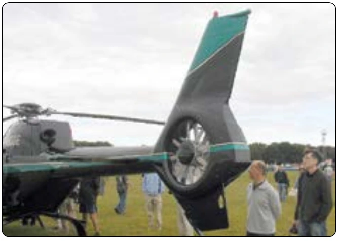
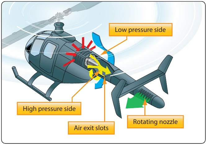
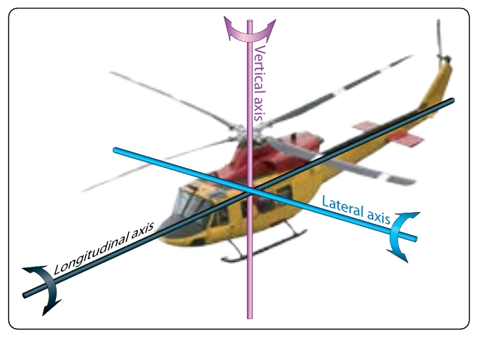
Some helicopters have a vertical stabilizer, such as those shown in Figures 5-90 and 5-92. In forward flight, the vertical stabilizer creates a force that helps counteract the torque of the main rotor, thereby reducing the power needed to drive the anti-torque system located at the end of the tail boom.
Control Around the Longitudinal and Lateral Axes
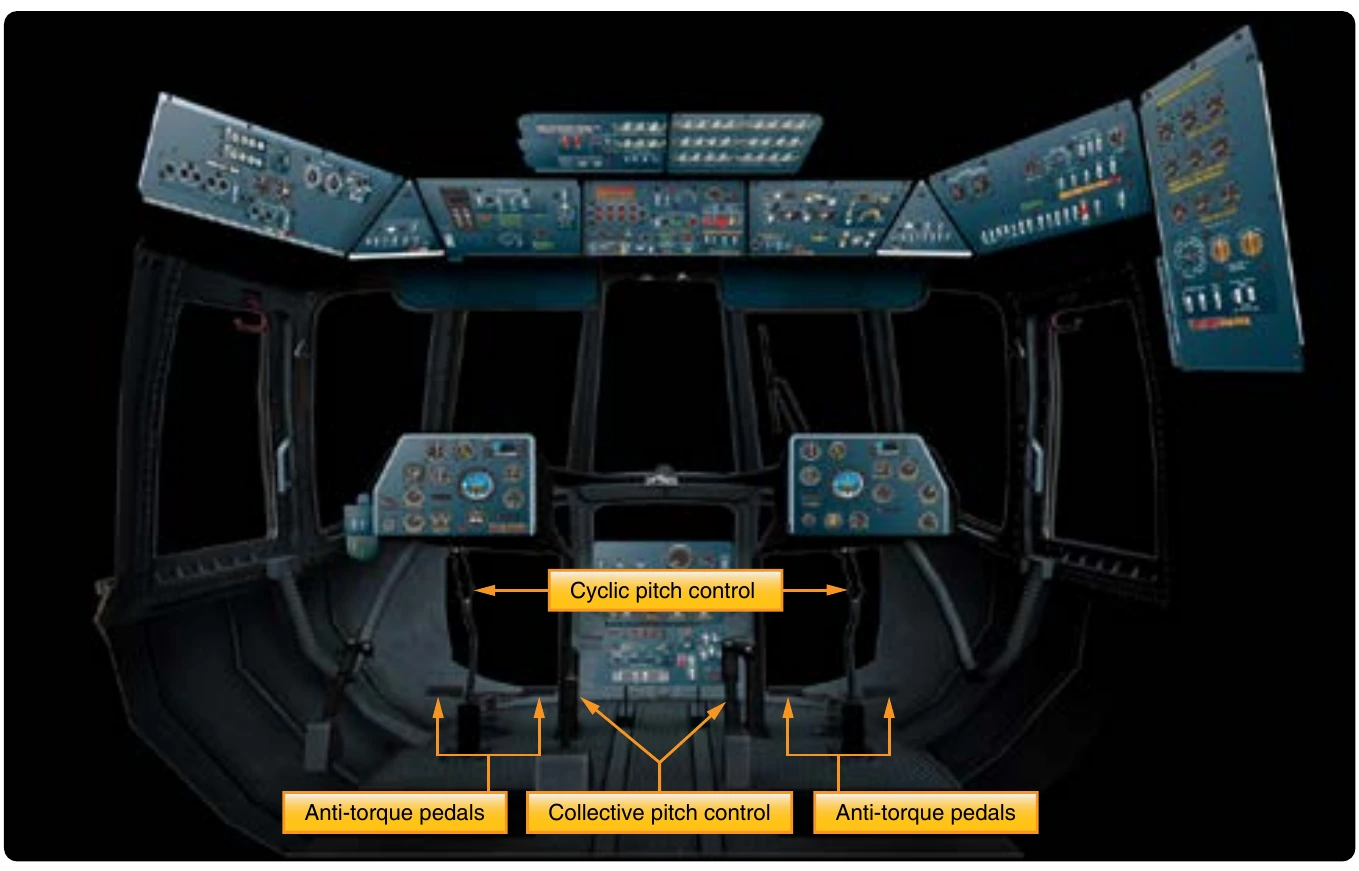
Movement around the longitudinal and lateral axes is handled by the helicopter’s main rotor. In the cockpit, there are two levers that control the main rotor, known as the collective and cyclic pitch controls. The collective pitch lever is on the side of the pilot’s seat, and the cyclic pitch lever is at the front of the seat in the middle. [Figure 5-91] When the collective pitch control lever is raised, the blade angle of all the rotor blades increases uniformly and they create the lift that allows the helicopter to take off vertically. The grip on the end of the collective pitch control is the throttle for the engine, which is rotated to increase engine power as the lever is raised. On many helicopters, the throttle automatically rotates and increases engine power as the collective lever is raised. The collective pitch lever may have adjustable friction built into it, so the pilot does not have to hold upward pressure on it during flight.
The cyclic pitch control lever, like the yoke of an airplane, can be pulled back or pushed forward, and can be moved left and right. When the cyclic pitch lever is pushed forward, the rotor blades create more lift as they pass through the back half of their rotation and less lift as they pass through the front half. The difference in lift is caused by changing the blade angle, or pitch, of the rotor blades. The pitch change rods that were seen earlier, in Figures 5-82 and 5-83, are controlled by the cyclic pitch lever and they are what change the pitch of the rotor blades. The increased lift in the back either causes the main rotor to tilt forward, the nose of the helicopter to tilt downward, or both. The end result is the helicopter moves in the forward direction. If the cyclic pitch lever is pulled back, the rotor blade lift will be greater in the front and the helicopter will back up.
If the cyclic pitch lever is moved to the left or the right, the helicopter will bank left or bank right. For the helicopter to bank to the right, the main rotor blades must create more lift as they pass by the left side of the helicopter. Just the opposite is true if the helicopter is banking to the left. By creating rotor blade in the rear and the one on the left are both in an upward raised position, meaning they have both experienced the condition called flap.
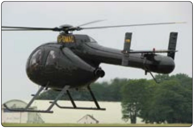
Some helicopters use a horizontal stabilizer, similar to what is seen on an airplane, to help provide additional stability around the lateral axis. A horizontal stabilizer can be seen on the Agusta A-109 in Figure 5-92.
Helicopters in Flight
Hovering
For a helicopter, hovering means that it is in flight at a constant altitude, with no forward, aft, or sideways movement. In order to hover, a helicopter must be producing enough lift in its main rotor blades to equal the weight of the aircraft. The engine of the helicopter must be producing enough power to drive the main rotor, and also to drive whatever type of anti-torque system is being used. The ability of a helicopter For a helicopter to experience ground effect, it typically needs to be no higher off the ground than one half of its main rotor system diameter. If a helicopter has a main rotor diameter of 40 ft., it will be in ground effect up to an altitude of approximately 20 ft. Being close to the ground affects the velocity of the air through the rotor blades, causing the effective angle of attack of the blades to increase and the lift to increase. So, if a helicopter is in ground effect, it can hover at a higher gross weight than it can when out of ground effect. On a windy day, the positive influence of ground effect is lessened, and at a forward speed of 5 to 10 mph the positive influence becomes less. In Figure 5-93, an Air Force CH-53 is seen in a hover, with all the rotor blades flapping up as a result of creating equal lift.
Forward Flight
In the early days of helicopter development, the ability to hover was mastered before there was success in attaining forward flight. The early attempts at forward flight resulted in the helicopter rolling over when it tried to depart from the hover and move in any direction. The cause of the rollover is what we now refer to as dissymmetry of lift.
When a helicopter is in a hover, all the rotor blades are experiencing the same velocity of airflow and the velocity of the airflow seen by the rotor blades changes when the helicopter starts to move. For helicopters built in the United States, the main rotor blades turn in a counterclockwise direction when viewed from the top. Viewed from the top, as the blades move around the right side of the helicopter, they are moving toward the nose; as they move around the left side of the helicopter, they are moving toward the tail. When the helicopter starts moving forward, the blade on the right side is moving toward the relative wind, and the blade on the left left side to create less lift. Figure 5-94 shows how this occurs. In Figure 5-94, blade number 2 would be called the advancing blade, and blade number 1 would be called the retreating blade. The advancing blade is moving toward the relative wind, and therefore experiences a greater velocity of airflow. The increased lift created by the blade on the right side will try to roll the helicopter to the left. If this condition is allowed to exist, it will ultimately lead to the helicopter crashing.
Blade Flapping
To solve the problem of dissymmetry of lift, helicopter designers came up with a hinged design that allows the rotor blade to flap up when it experiences increased lift, and to flap down when it experiences decreased lift. When a rotor blade advances toward the front of the helicopter and experiences an increased velocity of airflow, the increase in lift causes the blade to flap up. This upward motion of the blade changes the direction of the relative wind in relation to the chord line of the blade, and causes the angle of attack to decrease. The decrease in the angle of attack decreases the lift on the blade. The retreating blade experiences a reduced velocity of airflow and reduced lift, and flaps down. By flapping down, the retreating blade ends up with an increased angle of attack and an increase in lift. The end result is the lift on the blades is equalized, and the tendency for the helicopter to roll never materializes.