Chapter 7
Aircraft Materials, Hardware, & Processes
Head Styles
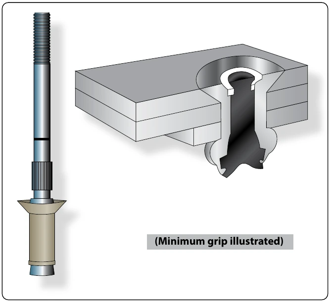
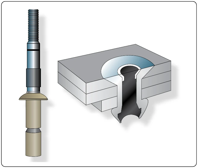
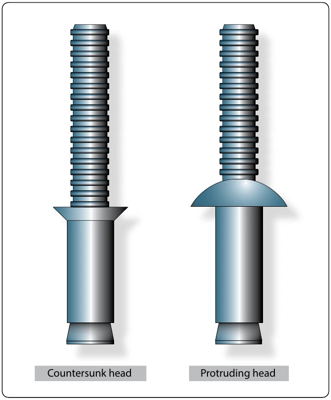
Self-plugging mechanical locked blind rivets are available in several head styles depending on the installation requirements. [Figure 7-47]
Diameters
Shank diameters are measured in 1⁄32-inch increments and are generally identified by the first dash number: -3 indicates 3⁄32 inch diameter, -4 indicates 1⁄8 diameter, and so forth. Both nominal and 1⁄64-inch oversize diameters are available.
Grip Length
Grip length refers to the maximum total sheet thickness to be riveted and is measured in 1⁄16 of an inch. This is generally identified by the second dash number. Unless otherwise noted, most blind rivets have their grip lengths (maximum grip) marked on the rivet head and have a total grip range of 1⁄16 inch. For example, –04 grip rivet has a grip range of 3⁄16" to 1⁄4". [Figure 7-48]
To determine the proper grip rivet to use, measure the material thickness with a grip selection gauge (available from blind rivet manufacturers). The proper use of a grip selector gauge is shown in Figure 7-49.
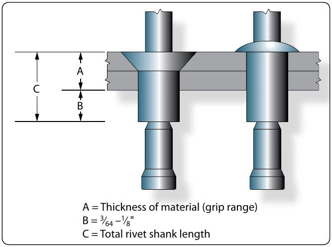
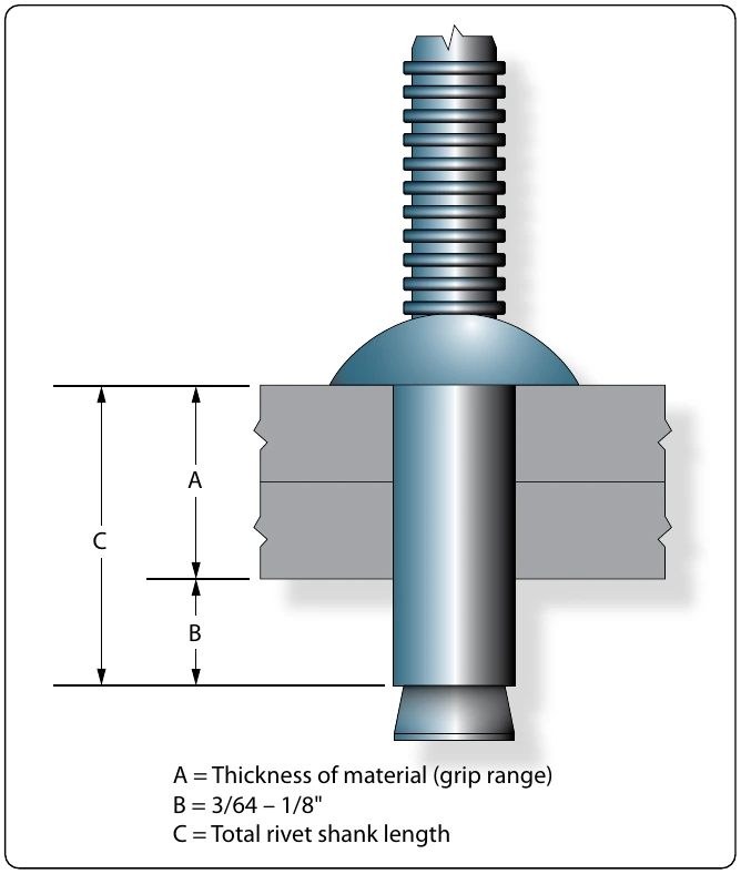
The thickness of the material being riveted determines the overall length of the shank of the rivet. As a general rule, the shank of the rivet should extend beyond the material thickness approximately 3⁄64 inch to 1⁄8 inch before the stem is pulled. [Figure 7-50] Each company that manufactures self-plugging (friction lock) rivets has a code number to help users obtain the correct rivet for the grip range or material thickness of a particular installation. In addition, MS numbers are used for identification purposes. Figures 7-51 through 7-54 contain examples of part numbers for self-plugging (friction lock) rivets that are representative of each.
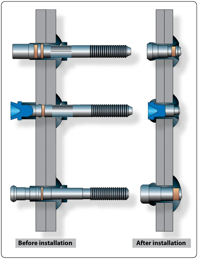
bolts and nuts. When AN bolts are tightened with the nut, the bolt stretches, narrowing the diameter and then the bolt is no longer tight in the hole. Special fasteners eliminate this loose fit, because they are held in place by a collar that is squeezed into position. These fasteners are not under the same tensile loads as a bolt during installation. Special fasteners are also used extensively for light sport aircraft (LSA). Always follow the aircraft manufacturer’s recommendations.
Pin Rivets
Pin (Hi-Shear) rivets are classified as special rivets but are not of the blind type. Access to both sides of the material is required to install this type of rivet. Pin rivets have the same shear strength as bolts of equal diameters, are about 40 percent of the weight of a bolt, and require only about one-fifth as much time for installation as a bolt, nut, and washer combination. They are approximately three times as strong as solid shank rivets.
Pin rivets are essentially threadless bolts. The pin is headed at one end and is grooved about the circumference at the other. A metal collar is swaged onto the grooved end effecting a firm, tight fit. [Figure 7-55] Pin rivets are fabricated in a variety of materials but should be used only in shear applications. They should never be used where the grip length is less than diameter and grip length of the individual rivets. A typical part number breakdown would be:
NAS177-14-17