Chapter 9
Fluid Lines & Fittings
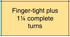
breaking hose clamps or damaging the hose, follow the hose clamp tightening instructions carefully. When available, use the hose clamp torque-limiting wrench. These wrenches are available in calibrations of 15 and 25 in-lb limits. In the absence of torque-limiting wrenches, follow the finger-tight-plus-turns method. Because of the variations in hose clamp design and hose structure, the values given in Figure 9-41 are approximate. Therefore, use good judgment when tightening hose clamps by this method. Since hose connections are subject to “cold flow” or a setting process, a follow-up tightening check should be made for several days after installation.
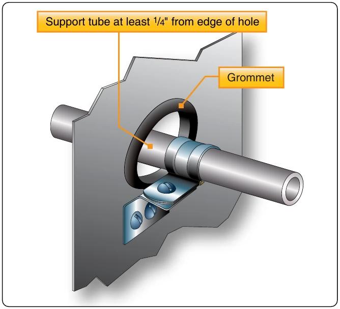
Support clamps are used to secure the various lines to the airframe or powerplant assemblies. Several types of support clamps are used for this purpose. The most commonly used clamps are the rubber-cushioned and plain. The rubber-cushioned clamp is used to secure lines subject to vibration; the cushioning prevents chafing of the tubing.
Ins I t O n a i n l t l i a l a y t l ion c W la o m rm p p e ( s r 1 c i 0 n r e c th w h r ) e ty a p d e s t r y a p d e C i p a l e ( l a 2 r a m 8 i n n p t d h c s r h o — e ) t a h d e s r
Self-sealing hose Finger-tight plus 2 Finger-tight plus approximately complete turns 2½ complete 15 in-lb turns
A Teflon™-cushioned clamp is used in areas where the deteriorating effect of Skydrol™, hydraulic fluid, or fuel is expected. However, because it is less resilient, it does not provide as good a vibration-damping effect as other cushion materials.
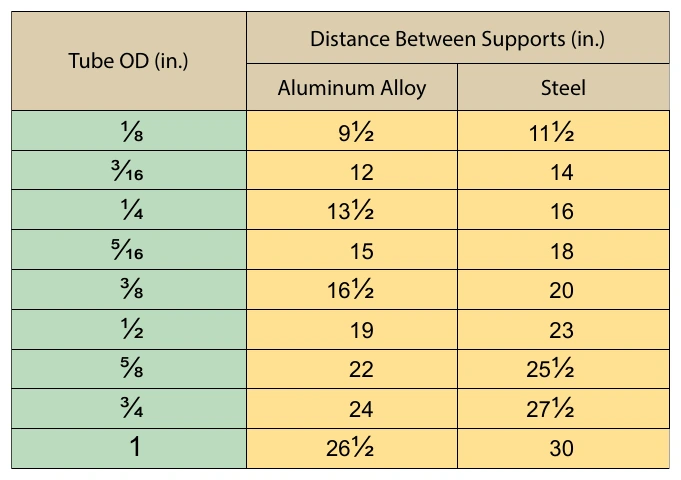
Use bonded clamps to secure metal hydraulic, fuel, or oil lines in place. Unbonded clamps should be used only for securing wiring. Remove any paint or anodizing from the portion of the tube at the bonding clamp location. Make certain that clamps are of the correct size. Clamps or supporting clips smaller than the outside diameter of the hose may restrict the flow of fluid through the hose. All fluid lines must be secured at specified intervals. The maximum distance between supports for rigid tubing is shown in Figure 9-43.