Chapter 9
Fluid Lines & Fittings
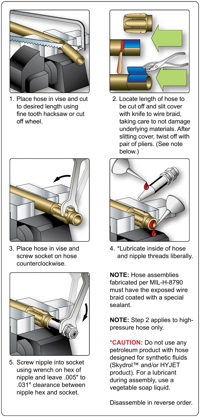
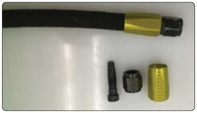


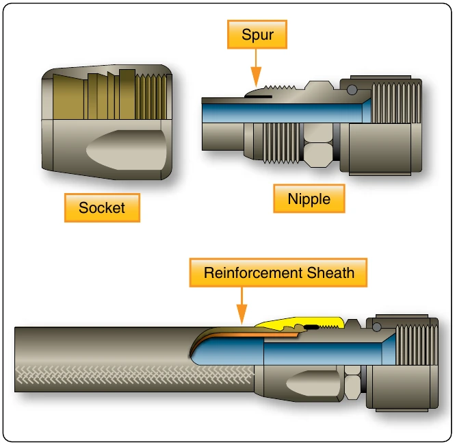
Installation of Flexible Hose Assemblies
Slack
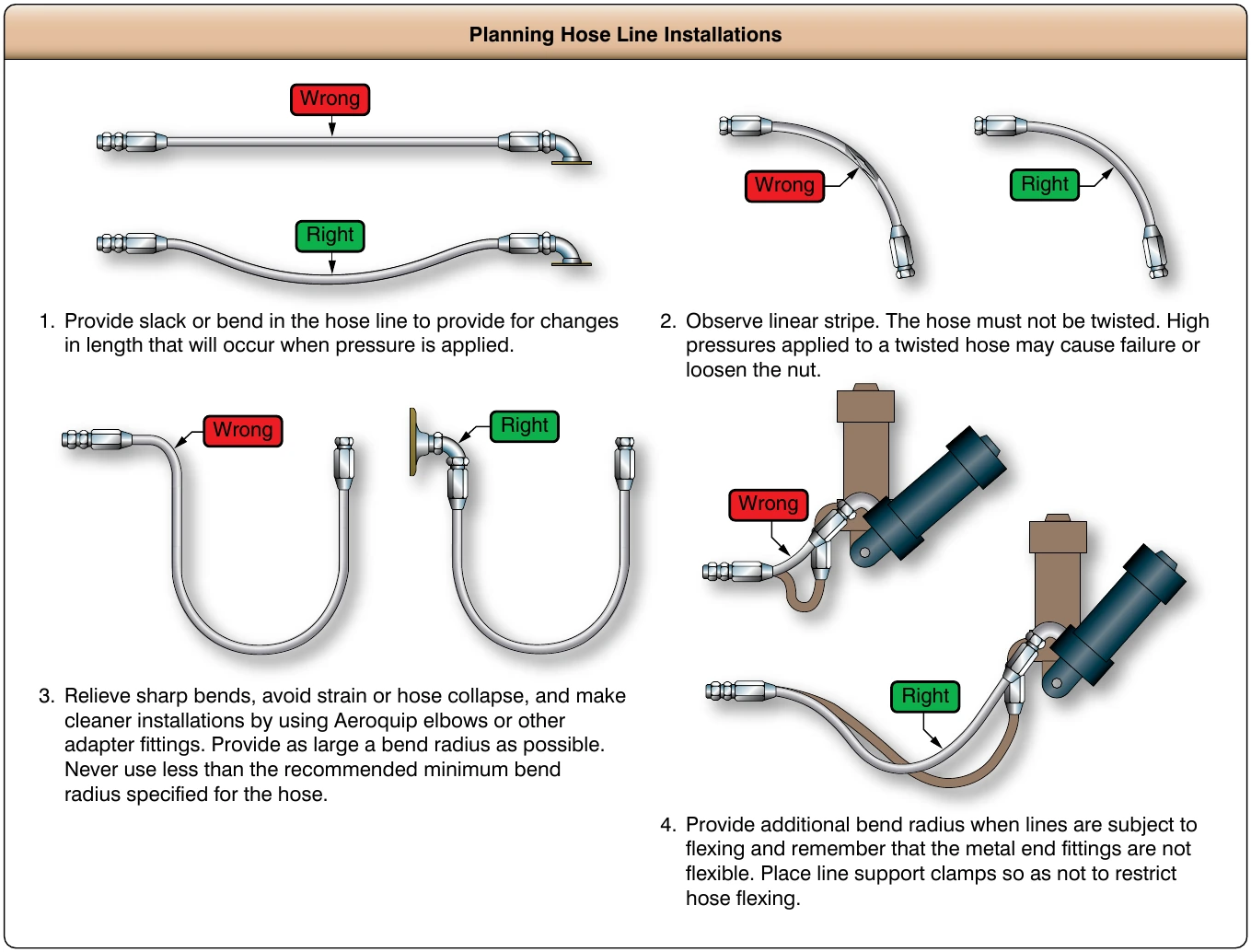
Hose assemblies must not be installed in a manner that causes a mechanical load on the hose. When installing flexible hose, provide slack or bend in the hose line from 5 to 8 percent of its total length to provide for changes in length that occurs when pressure is applied. Flexible hose contracts in length and expands in diameter when pressurized. Protect all flexible hoses from excessive temperatures, either by locating the lines so they are not affected or by installing shrouds around them.
Flex
When hose assemblies are subject to considerable vibration or flexing, sufficient slack must be left between rigid fittings. Install the hose so that flexure does not occur at the end fittings. The hose must remain straight for at least two hose diameters from the end fittings. Avoid clamp locations that restrict or prevent hose flexure.
Twisting
Hoses must be installed without twisting to avoid possible rupture of the hose or loosening of the attaching nuts. Use of swivel connections at one or both ends relieve twist stresses. Twisting of the hose can be determined from the identification
Bending
To avoid sharp bends in the hose assembly, use elbow fittings, hose with elbow-type end fittings, or the appropriate bend radii. Bends that are too sharp reduce the bursting pressure of flexible hose considerably below its rated value. [Figure 9-40]
Clearance
The hose assembly must clear all other lines, equipment, and adjacent structure under every operating condition.
Flexible hose should be installed so that it is subject to a minimum of flexing during operation. Although hose must be supported at least every 24 inches, closer supports are desirable. Flexible hose must never be stretched tightly between two fittings. If clamps do not seal at specified tightening, examine hose connections and replace parts as necessary. The above is for initial installation and should not be used for loose clamps.
For retightening loose hose clamps in service, proceed as follows:
- Non-self-sealing hose—if the clamp screw cannot be tightened with the fingers, do not disturb unless leakage is evident. If leakage is present, tighten one-fourth turn.
- Self-sealing hose—if looser than finger-tight, tighten to finger-tight and add one-fourth turn. [Figure 9-41]