Chapter 9
Fluid Lines & Fittings
Fabrication of Metal Tube Lines
Damaged tubing and fluid lines should be repaired with new parts whenever possible. Unfortunately, sometimes replacement is impractical and repair is necessary. Scratches, abrasions, or minor corrosion on the outside of fluid lines may be considered negligible and can be smoothed out with a burnishing tool or aluminum wool. Limitations on the amount of damage that can be repaired in this manner are discussed in this chapter under “Rigid Tubing Inspection and Repair.” If a fluid line assembly is to be replaced, the fittings can often be salvaged; then the repair involves only tube forming and replacement.
Tube forming consists of four processes: cutting, bending, flaring, and beading. If the tubing is small and made of soft material, the assembly can be formed by hand bending during installation. If the tube is 1⁄4" diameter or larger, hand bending without the aid of tools is impractical.
Tube Cutting
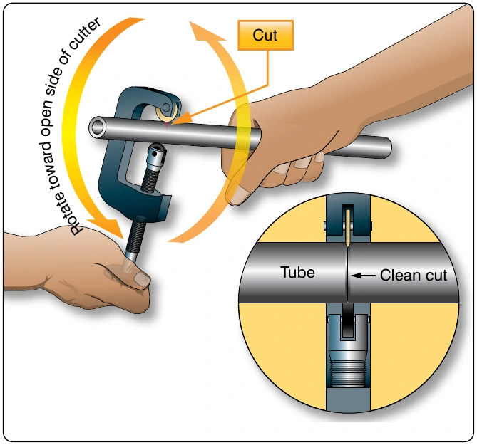
When cutting tubing, it is important to produce a square end, free of burrs. Tubing may be cut with a tube cutter or a hacksaw. The cutter can be used with any soft metal tubing, such as copper, aluminum, or aluminum alloy. Correct use of the tube cutter is shown in Figure 9-2. Special chipless cutters are available for cutting aluminum 6061-T6, corrosion-resistant steel, and titanium tubing.
A new piece of tubing should be cut approximately 10 percent longer than the tube to be replaced to provide for minor variations in bending. Place the tube in the cutting tool with the cutting wheel at the point where the cut is to be made. Rotate the cutter around the tubing, applying light pressure to the cutting wheel by intermittently twisting the thumbscrew.
Too much pressure on the cutting wheel at one time could deform the tubing or cause excessive burring. After cutting the tubing, carefully remove any burrs from inside and outside the tube. Use a knife or the burring edge attached to the tube cutter. The deburring operation can be accomplished by the use of a deburring tool. [Figure 9-3] This tool is capable of removing both the inside and outside burrs by just turning the tool end for end.
When performing the deburring operation, use extreme care that the wall thickness of the end of the tubing is not reduced or fractured. Very slight damage of this type can lead to fractured flares or defective flares, which do not seal properly. Use a fine-tooth file to file the end square and smooth.
If a tube cutter is not available, or if tubing of hard material is to be cut, use a fine-tooth hacksaw, preferably one having 32 teeth per inch. The use of a saw decreases the amount of work hardening of the tubing during the cutting operation. After sawing, file the end of the tube square and smooth, removing all burrs.
An easy way to hold small diameter tubing, when cutting it, is to place the tube in a combination flaring tool and clamp the tool in a vise. Make the cut about one-half inch from the flaring tool. This procedure keeps sawing vibrations to a minimum and prevents damage to the tubing if it is accidentally hit with the hacksaw frame or file handle while cutting. Be sure all filings and cuttings are removed from the tube.
Tube Bending
The objective in tube bending is to obtain a smooth bend without flattening the tube. Tubing under 1⁄4" in diameter usually can be bent without the use of a bending tool. For larger sizes, either portable hand benders or production benders are usually used. Figure 9-4 shows preferred methods and standard bend radii for bending tubing by tube size.
Using a hand bender, insert the tubing into the groove of the bender so that the measured end is left of the form block. Align the two zeros and align the mark on the tubing with the L on the form handle. If the measured end is on the right side, then align the mark on the tubing with the R on the form handle. With a steady motion, pull the form handle until the zero mark on the form handle lines up with the desired angle of bend, as indicated on the radius block. [Figure 9-5]
Hand benders come in different sizes that correspond to the tube diameter. Make sure to select the correct bender for the desired tube diameter. Figure 9-6 shows hand benders available for different sizes of tubing. Typically, the tubing size is stamped in the bender. [Figure 9-7]
Bend the tubing carefully to avoid excessive flattening, kinking, or wrinkling. A small amount of flattening in bends is acceptable, but the small diameter of the flattened portion must not be less than 75 percent of the original outside diameter. Tubing with flattened, wrinkled, or irregular bends should not be installed. Wrinkled bends usually result from trying to bend thin wall tubing without using a tube bender. Excessive flattening causes fatigue failure of the tube. Examples of correct and incorrect tubing bends are shown in Figure 9-8.
Tube bending machines for all types of tubing are generally used in repair stations and large maintenance shops. With such equipment, proper bends can be made on large diameter tubing and on tubing made from hard material. The production CNC™ tube bender is an example of this type of machine. [Figure 9-9] The ordinary production tube bender accommodates tubing ranging from 1⁄4" to 11⁄2" outside diameter. Benders for larger sizes are available, and the principle of their operation is similar to that of the hand tube bender. The radius blocks are so constructed that the radius of bend varies with the tube diameter. The radius of bend is usually stamped on the block.