
Chapter 9
Fluid Lines & Fittings
When hand or production tube benders are not available or are not suitable for a particular bending operation, a filler of metallic composition or of dry sand may be used to facilitate bending. When using this method, cut the tube slightly longer than required. The extra length is for inserting a plug (which may be wooden) in each end. The tube can also be closed by flattening the ends or by soldering metal disks in them.
After plugging one end, fill and pack the tube with fine, dry sand and plug tightly. Both plugs must be tight so they are not forced out when the bend is made. After the ends are closed, bend the tubing over a forming block shaped to the specified radius. In a modified version of the filler method, a fusible alloy is used instead of sand. In this method, the tube is filled under hot water with a fusible alloy that melts at 160 °F. The alloy-filled tubing is then removed from the water, allowed to cool, and bent slowly by hand around a forming block or with a tube bender. After the bend is made, the alloy is again melted under hot water and removed from the tubing. When using either filler methods, make certain that all particles of the filler are removed. Visually inspect with a borescope to make certain that no particles are carried into the system in which the tubing is installed. Store the fusible alloy filler where it is free from dust or dirt. It can be re-melted and reused as often as desired. Never heat this filler in any other way than the prescribed method, as the alloy will stick to the inside of the tubing, making them both unusable.
Tube Flaring
Two kinds of flares are generally used in aircraft tubing: the connection leaks or fails. A flare made too small produces a weak joint, which may leak or pull apart; if made too large, it interferes with the proper engagement of the screw thread on the fitting and causes leakage. A crooked flare is the result of the tubing not being cut squarely. If a flare is not made properly, flaws cannot be corrected by applying additional torque when tightening the fitting. The flare and tubing must be free from cracks, dents, nicks, scratches, or any other defects.
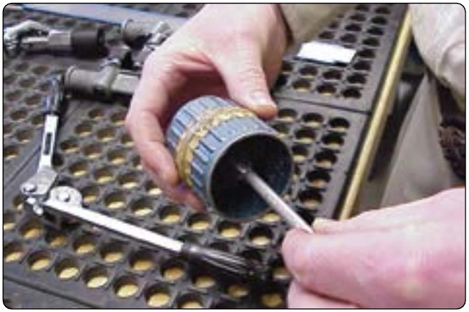
The flaring tool used for aircraft tubing has male and female dies ground to produce a flare of 35° to 37°. Under no circumstance is it permissible to use an automotive-type flaring tool that produces a flare of 45°. [Figure 9-11]
The single-flare hand flaring tool, similar to that shown in Figure 9-12, is used for flaring tubing. The tool consists of a flaring block or grip die, a yoke, and a flaring pin. The flaring block is a hinged double bar with holes corresponding to various sizes of tubing. These holes are countersunk on one end to form the outside support against which the flare is formed. The yoke is used to center the flaring pin over the end of the tube to be flared. Two types of flaring tools are used to make flares on tubing: the impact type and the rolling type.
Instructions for Rolling-Type Flaring Tools
Use these tools only to flare soft copper, aluminum, and brass tubing. Do not use with corrosion-resistant steel or titanium.
ous sizes of tubes.
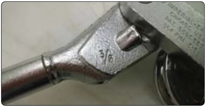
locking the sliding segment in the die holder. This permits their separation. The tools are self-gauging; the proper size Advance the clamp screw against the end segment and tighten firmly. Move the yoke down over the top of the die holder and twist it clockwise to lock it into position. Turn the feed screw down firmly, and continue until a slight resistance is felt. This indicates an accurate flare has been completed. Always read the tool manufacturer’s instructions, because there are several different types of rolling-type flaring tools that use slightly different procedures.
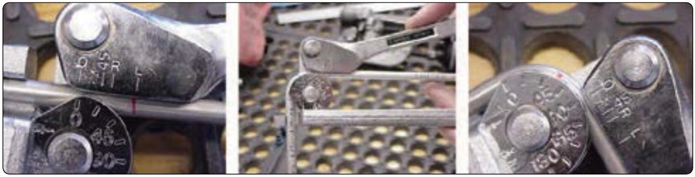
Double Flaring
A double flare is used on soft aluminum alloy tubing 3⁄8" outside diameter and under. This is necessary to prevent cutting off the flare and failure of the tube assembly under operating pressures. A double flare is smoother and more concentric than a single flare and therefore seals better. It is also more resistant to the shearing effect of torque.
Double Flaring Instructions
Deburr both the inside and outside of the tubing to be flared. Cut off the end of the tubing if it appears damaged. Anneal brass, copper, and aluminum by heating to a dull red and cool end you have just prepared, extending above the top of the bar by a distance equal to the thickness of the shoulder of the adapter insert. Tighten clamping screws to hold tubing securely. Insert pilot of correctly sized adapter into tubing. Slip yoke over the flaring bars and center over adapter. Advance the cone downward until the shoulder of the adapter rests on the flaring bar. This bells out the end of the tubing. Next, back off the cone just enough to remove the adapter. After removing the adapter, advance the cone directly into the belled end of the tubing. This folds the tubing on itself and forms an accurate double flare without cracking or splitting the tubing. To prevent thinning out of the flare wall, do not overtighten. [Figure 9-13]