Chapter 1
Aircraft Engines
The valve lift (distance that the valve is lifted off its seat) and the valve duration (length of time the valve is held open) are both determined by the shape of the cam lobes. Typical cam lobes are illustrated in Figure 1-23. The portion of the lobe that gently starts the valve operating mechanism moving is called a ramp, or step. The ramp is machined on each side of
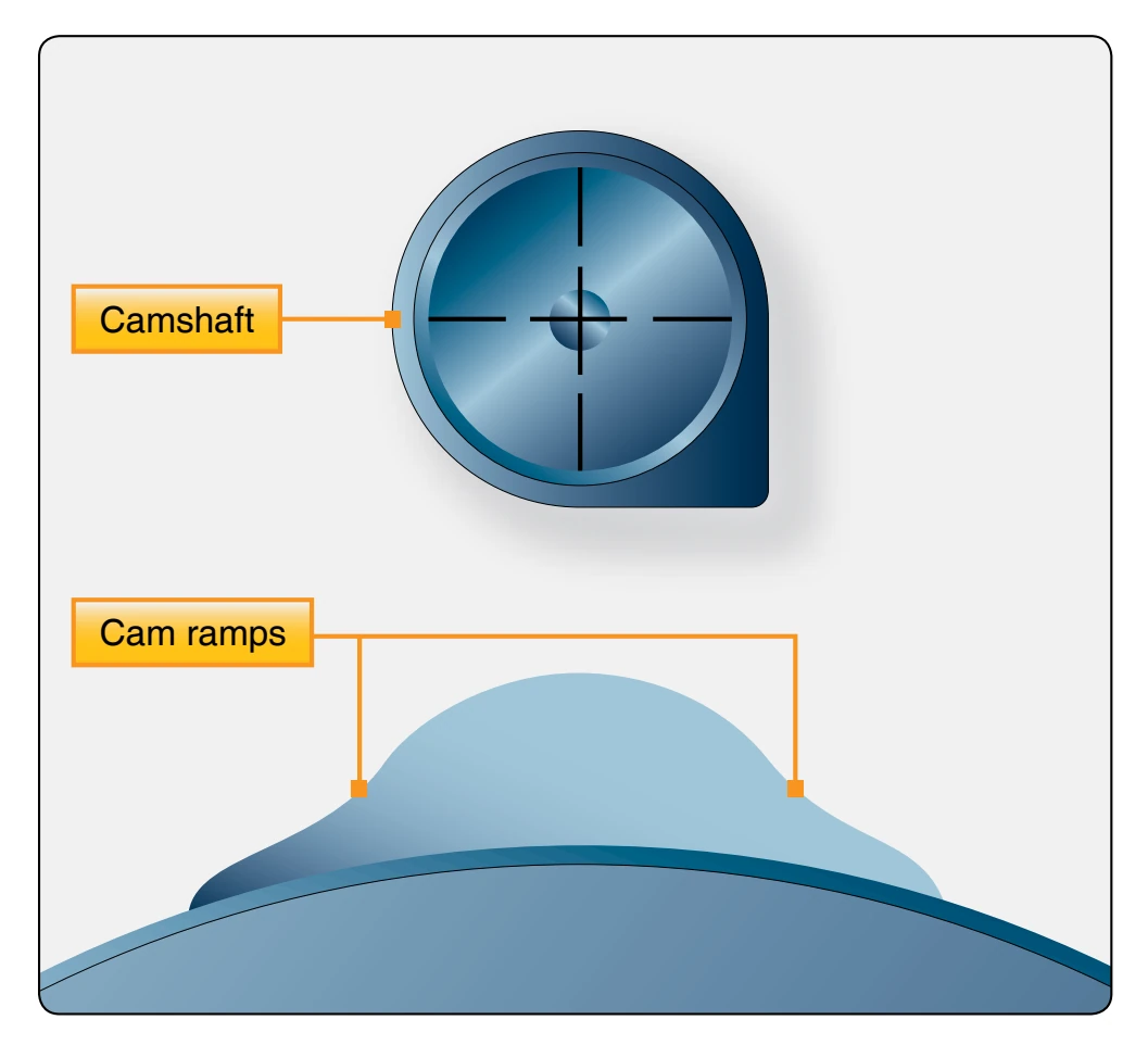
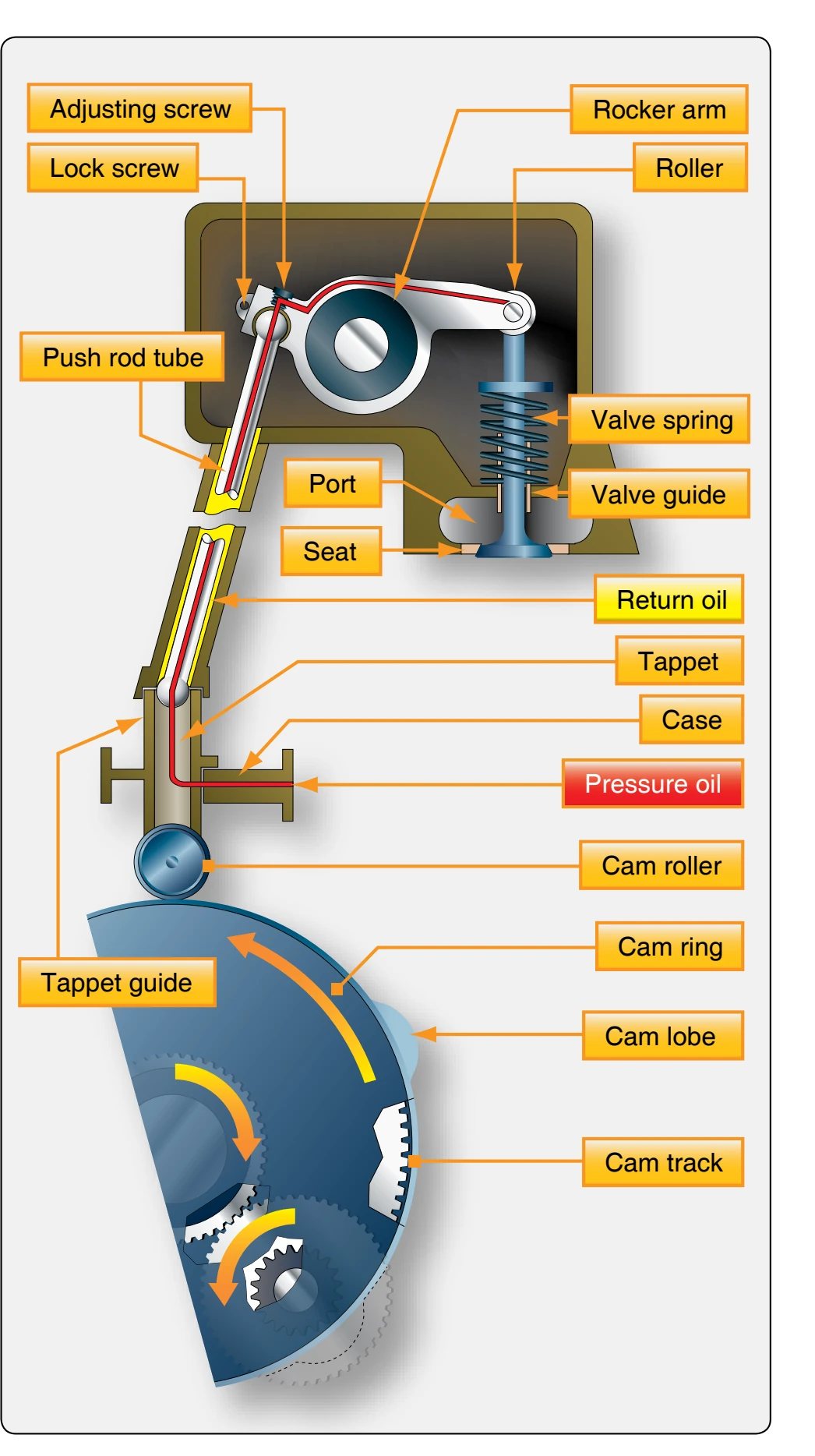
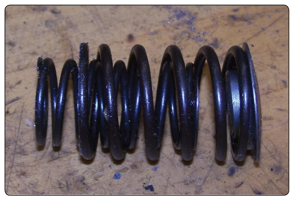
the cam lobe to permit the rocker arm to be eased into contact with the valve tip and thus reduce the shock load which would otherwise occur. The valve operating mechanism consists of a cam ring or camshaft equipped with lobes that work against a cam roller or a cam follower. [Figures 1-24 and 1-25] The cam follower pushes a push rod and ball socket, actuating a rocker arm, which in turn opens the valve. Springs, which slip over the stem of the valves and are held in place by the valve-spring retaining washer and stem key, close each valve and push the valve mechanism in the opposite direction. [Figure 1-26]
Cam Rings
The valve mechanism of a radial engine is operated by one or two cam rings, depending upon the number of rows of cylinders. In a single-row radial engine, one ring with a double cam track is used. One track operates the intake valves, the other
operates the exhaust valves. The cam ring is a circular piece of steel with a series of cams or lobes on the outer surface. The surface of these lobes and the space between them (on which the cam rollers ride) is known as the cam track. As the cam ring revolves, the lobes cause the cam roller to raise the tappet in the tappet guide, thereby transmitting the force through the push rod and rocker arm to open the valve. In a single-row radial engine, the cam ring is usually located between the propeller reduction gearing and the front end of the power section. In a twin-row radial engine, a second cam for the operation of the valves in the rear row is installed between the rear end of the power section and the supercharger section.
The cam ring is mounted concentrically with the crankshaft and is driven by the crankshaft at a reduced rate of speed
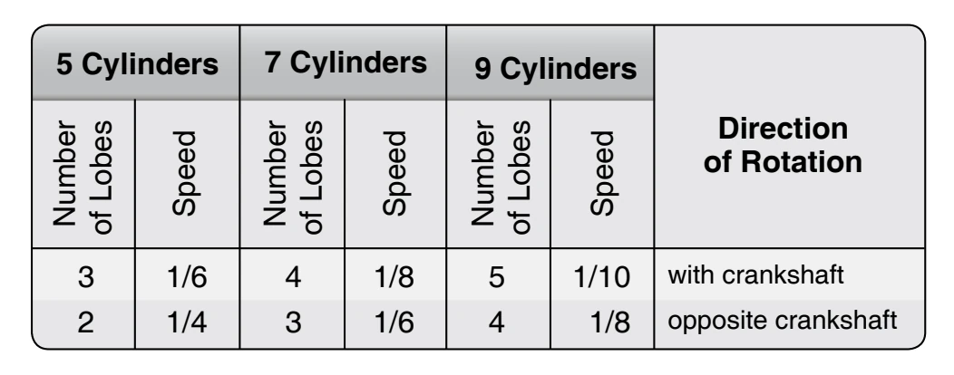
through the cam intermediate drive gear assembly. The cam ring has two parallel sets of lobes spaced around the outer periphery, one set (cam track) for the intake valves and the other for the exhaust valves. The cam rings used may have four or five lobes on both the intake and the exhaust tracks. The timing of the valve events is determined by the spacing of these lobes and the speed and direction at which the cam rings are driven in relation to the speed and direction of the crankshaft. The method of driving the cam varies on different makes of engines. The cam ring can be designed with teeth on either the inside or outside periphery. If the reduction gear meshes with the teeth on the outside of the ring, the cam turns in the direction of rotation of the crankshaft. If the ring is driven from the inside, the cam turns in the opposite direction from the crankshaft. [Figure 1-24]
A four-lobe cam may be used on either a seven-cylinder or nine-cylinder engine. [Figure 1-27] On the seven cylinder, it rotates in the same direction as the crankshaft, and on the nine cylinder, opposite the crankshaft rotation. On the ninecylinder engine, the spacing between cylinders is 40° and the firing order is 1-3-5-7-9-2-4-6-8. This means that there is a space of 80° between firing impulses. The spacing on the four lobes of the cam ring is 90°, which is greater than the spacing between impulses. Therefore, to obtain proper relation of valve operations and firing order, it is necessary to drive the cam opposite the crankshaft rotation. Using the four-lobe cam on the seven-cylinder engine, the spacing between the firing of the cylinders is greater than the spacing of the cam lobes. Therefore, it is necessary for the cam to rotate in the same direction as the crankshaft.
Camshaft
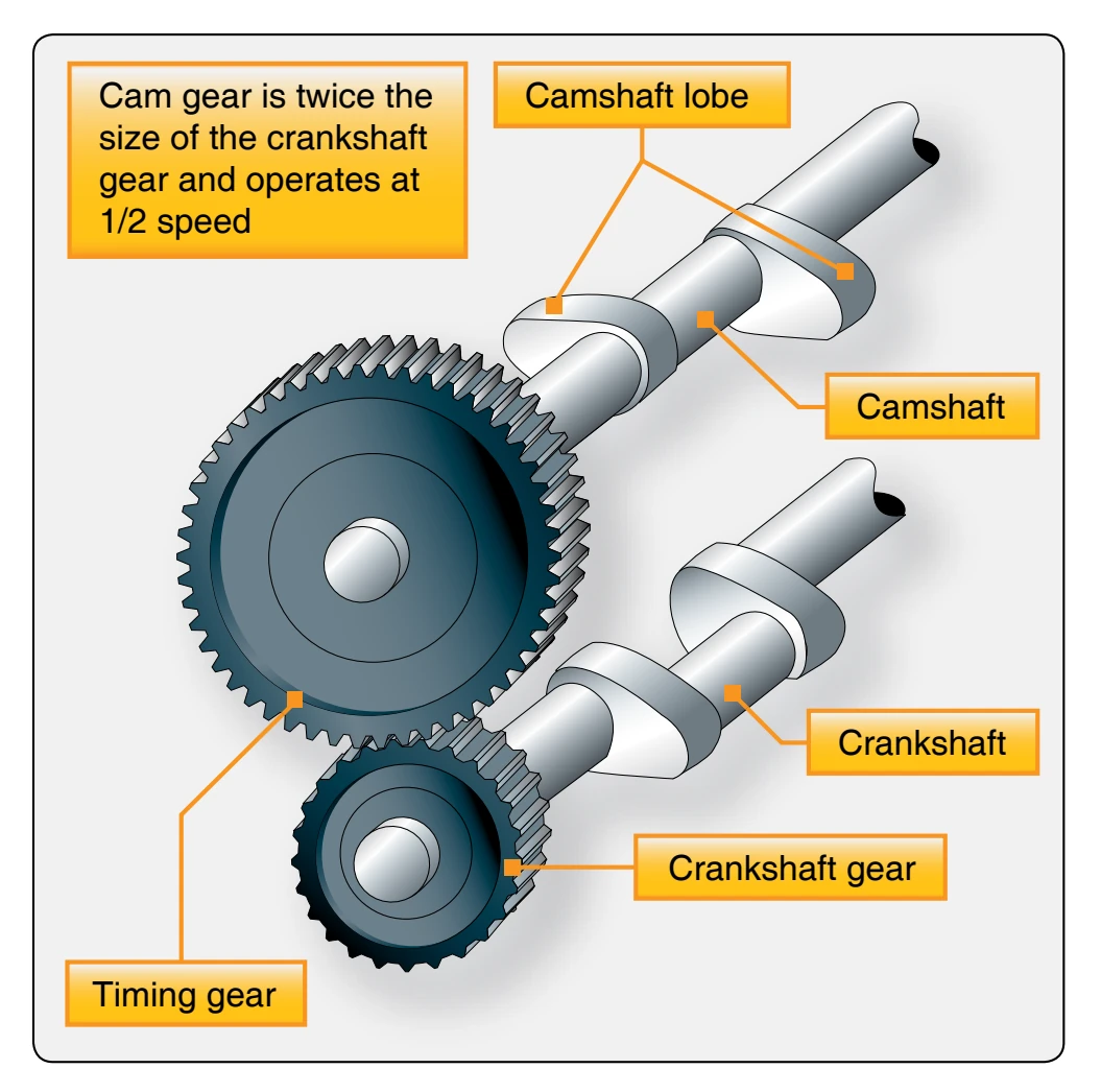
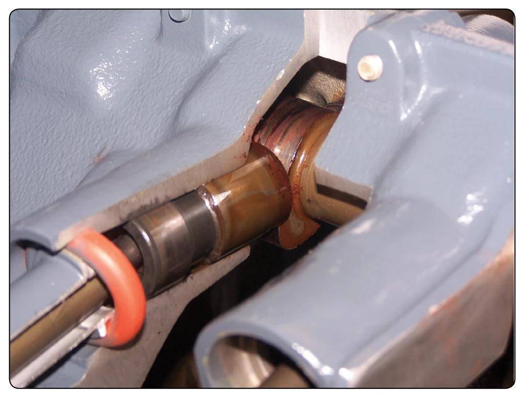
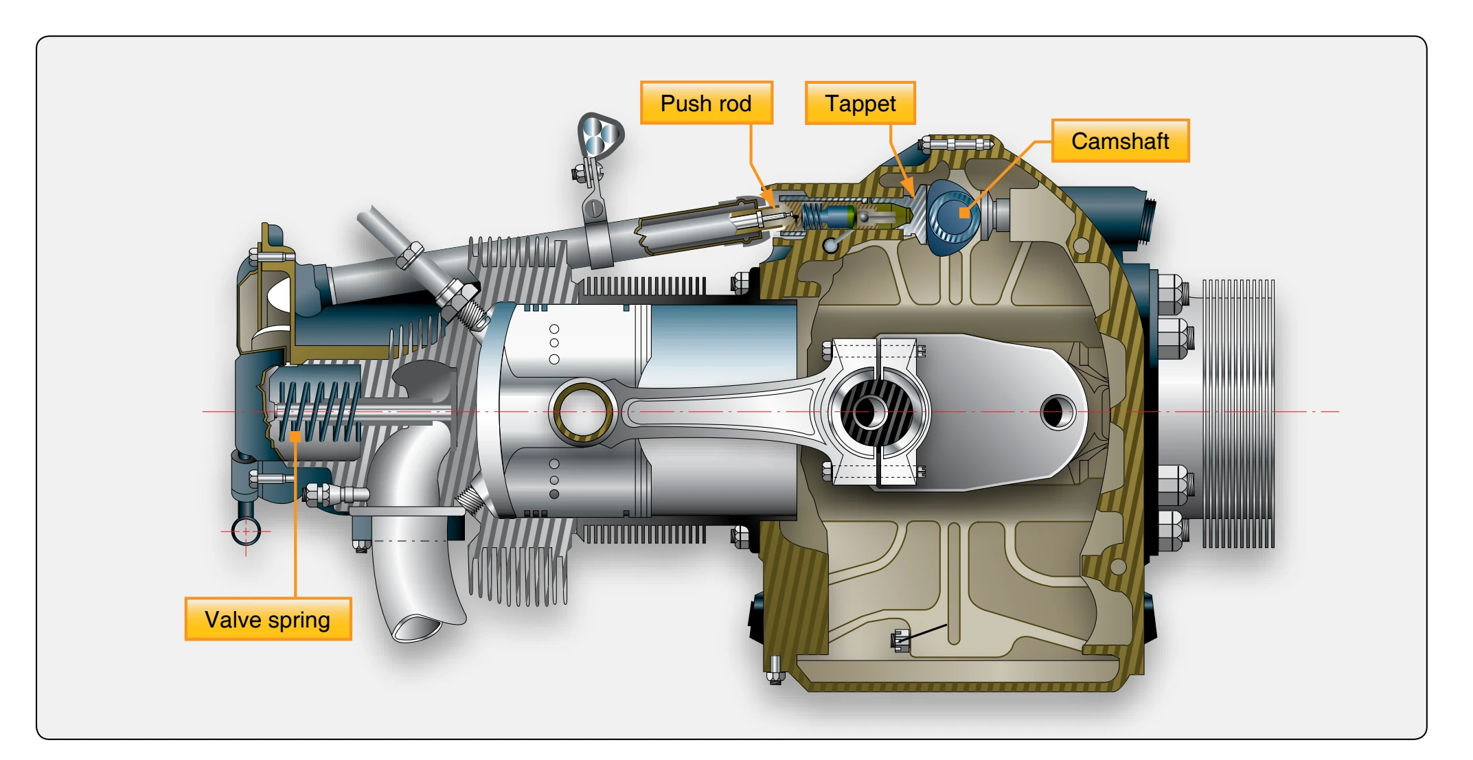
The valve mechanism of an opposed engine is operated by a camshaft. The camshaft is driven by a gear that mates with another gear attached to the crankshaft. [Figure 1-28] The camshaft always rotates at one-half the crankshaft speed. As the camshaft revolves, the lobes cause the tappet assembly to rise in the tappet guide, transmitting the force through the push rod and rocker arm to open the valve. [Figure 1-29]
Tappet Assembly
The tappet assembly consists of:
- A cylindrical tappet, which slides in and out in a tappet guide installed in one of the crankcase sections around the cam ring;
- A tappet roller, which follows the contour of the cam ring and lobes;
- A tappet ball socket or push rod socket; and
- A tappet spring.