
Chapter 1
Aircraft Engines
The function of the tappet assembly is to convert the rotational movement of the cam lobe into reciprocating motion and to transmit this motion to the push rod, rocker arm, and then to the valve tip, opening the valve at the proper time. The purpose of the tappet spring is to take up the clearance between the rocker arm and the valve tip to reduce the shock load when the valve is opened. A hole is drilled through the tappet to allow engine oil to flow to the hollow push rods to lubricate the rocker assemblies.
Solid Lifters/Tappets
Solid lifters or cam followers generally require the valve clearance to be adjusted manually by adjusting a screw and lock nut. Valve clearance is needed to assure that the valve has enough clearance in the valve train to close completely. This adjustment or inspection was a continuous maintenance item until hydraulic lifters were used.
Hydraulic Valve Tappets/Lifters
Some aircraft engines incorporate hydraulic tappets that automatically keep the valve clearance at zero, eliminating the necessity for any valve clearance adjustment mechanism. A typical hydraulic tappet (zero-lash valve lifter) is shown in Figure 1-30.
When the engine valve is closed, the face of the tappet body (cam follower) is on the base circle or back of the cam. [Figure 1-30] The light plunger spring lifts the hydraulic plunger so that its outer end contacts the push rod socket, exerting a light pressure against it, thus eliminating any clearance in the valve linkage. As the plunger moves outward, the ball check valve moves off its seat. Oil from the supply chamber, which is directly connected with the engine lubrication system, flows in and fills the pressure chamber. As the camshaft rotates, the cam pushes the tappet body and the
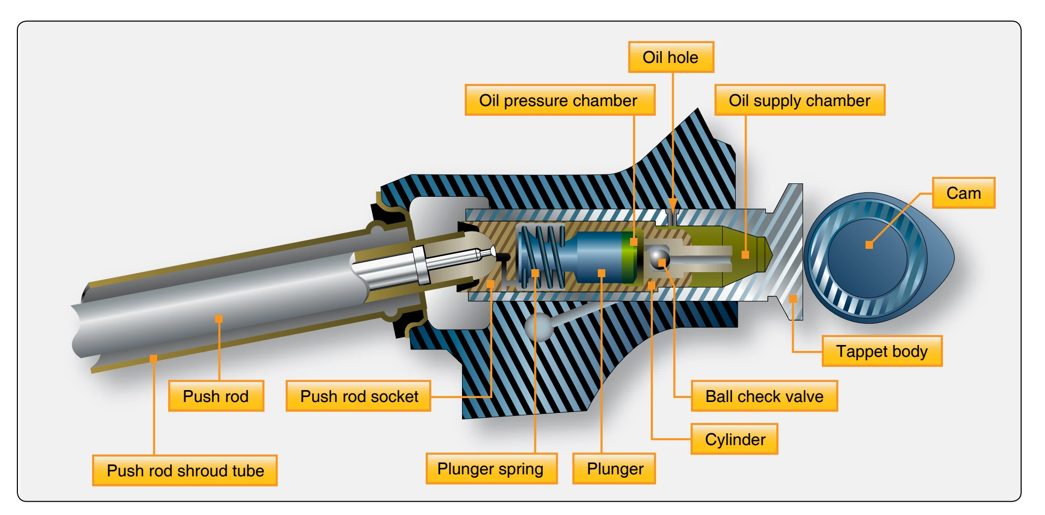
hydraulic lifter cylinder outward. This action forces the ball check valve onto its seat; thus, the body of oil trapped in the pressure chamber acts as a cushion. During the interval when the engine valve is off its seat, a predetermined leakage occurs between plunger and cylinder bore, which compensates for any expansion or contraction in the valve train. Immediately after the engine valve closes, the amount of oil required to fill the pressure chamber flows in from the supply chamber, preparing for another cycle of operation.
Hydraulic valve lifters are normally adjusted at the time of overhaul. They are assembled dry (no lubrication), clearances checked, and adjustments are usually made by using push rods of different lengths. A minimum and maximum valve clearance is established. Any measurement between these extremes is acceptable, but approximately half way between the extremes is desired. Hydraulic valve lifters require less maintenance, are better lubricated, and operate more quietly than the screw adjustment type.
Push Rod
The push rod, tubular in form, transmits the lifting force from the valve tappet to the rocker arm. A hardened-steel ball is pressed over or into each end of the tube. One ball end fits into the socket of the rocker arm. In some instances, the balls are on the tappet and rocker arm, and the sockets are on the push rod. The tubular form is employed because of its lightness and strength. It permits the engine lubricating oil under pressure to pass through the hollow rod and the drilled ball ends to lubricate the ball ends, rocker-arm bearing, and valve-stem guide. The push rod is enclosed in a tubular housing that extends from the crankcase to the cylinder head, referred to as push rod tubes.
Rocker Arms
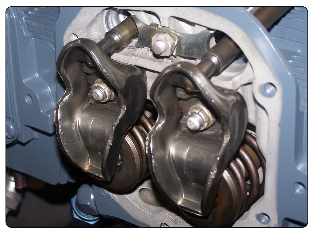
The rocker arms transmit the lifting force from the cams to the valves. [Figure 1-31] Rocker arm assemblies are supported by a plain, roller, or ball bearing, or a combination of these, which serves as a pivot. Generally, one end of the arm bears against the push rod and the other bears on the valve stem. One end of the rocker arm is sometimes slotted to accommodate a steel roller. The opposite end is constructed with either a threaded split clamp and locking bolt or a tapped hole. The arm may have an adjusting screw, for adjusting the clearance between the rocker arm and the valve stem tip. The screw can be adjusted to the specified clearance to make certain that the valve closes fully.
Valve Springs
Each valve is closed by two or three helical springs. If a single spring were used, it would vibrate or surge at certain speeds. To eliminate this difficulty, two or more springs (one inside the other) are installed on each valve. Each spring vibrates at a different engine speed and rapid damping out of all spring-surge vibrations during engine operation results. Two or more springs also reduce danger of weakness and possible failure by breakage due to heat and metal fatigue. The springs are held in place by split locks installed in the recess of the valve spring upper retainer or washer, and engage a groove machined into the valve stem. The functions of the valve springs are to close the valve and to hold the valve securely on the valve seat.
Bearings
A bearing is any surface which supports, or is supported by, another surface. A good bearing must be composed of material that is strong enough to withstand the pressure imposed on it and should permit the other surface to move with a minimum of friction and wear. The parts must be held in position within very close tolerances to provide efficient and quiet operation, and yet allow freedom of motion. Lubricated bearings of many types are used to accomplish this, and at the same time reduce friction of moving parts so that power loss is not excessive and to prevent high oil temperatures caused by failed or failing bearings. Bearings are required to take radial loads, thrust loads, or a combination of the two. An example of a radial load would be a rotating shaft being held or contained in one position on a radial plane. Thrust load would be the rotating shaft being contained from moving axially along the shafts axis. These radial and thrust loads are illustrated in Figure 1-32. There are two ways in which bearing surfaces move in relation to each other. One is by the sliding movement of one metal against the other (sliding friction), and the second is for one surface to roll over the other (rolling friction). The three different types of bearings in general use are plain, roller, and ball. [Figure 1-33]
Plain Bearings
Plain bearings are generally used for the crankshaft, cam ring, camshaft, connecting rods, and the accessory drive shaft bearings. Such bearings are usually subjected to radial loads only, although some have been designed to take thrust loads. Plain bearings are usually made of nonferrous (having no iron) metals, such as silver, bronze, aluminum, and various alloys of copper, tin, or lead. Master rod or crankpin bearings in some engines are thin shells of steel, plated with silver on both the inside and the outside surfaces and with lead-tin plated over the silver on the inside surface only. Smaller bearings, such as those used to support various shafts in the accessory section, are called bushings. Porous Oilite bushings are widely used in this instance. They are impregnated with oil so that the heat of friction brings the oil to the bearing surface during engine operation.