
Chapter 1
Aircraft Engines
Double-Row Radial Engines
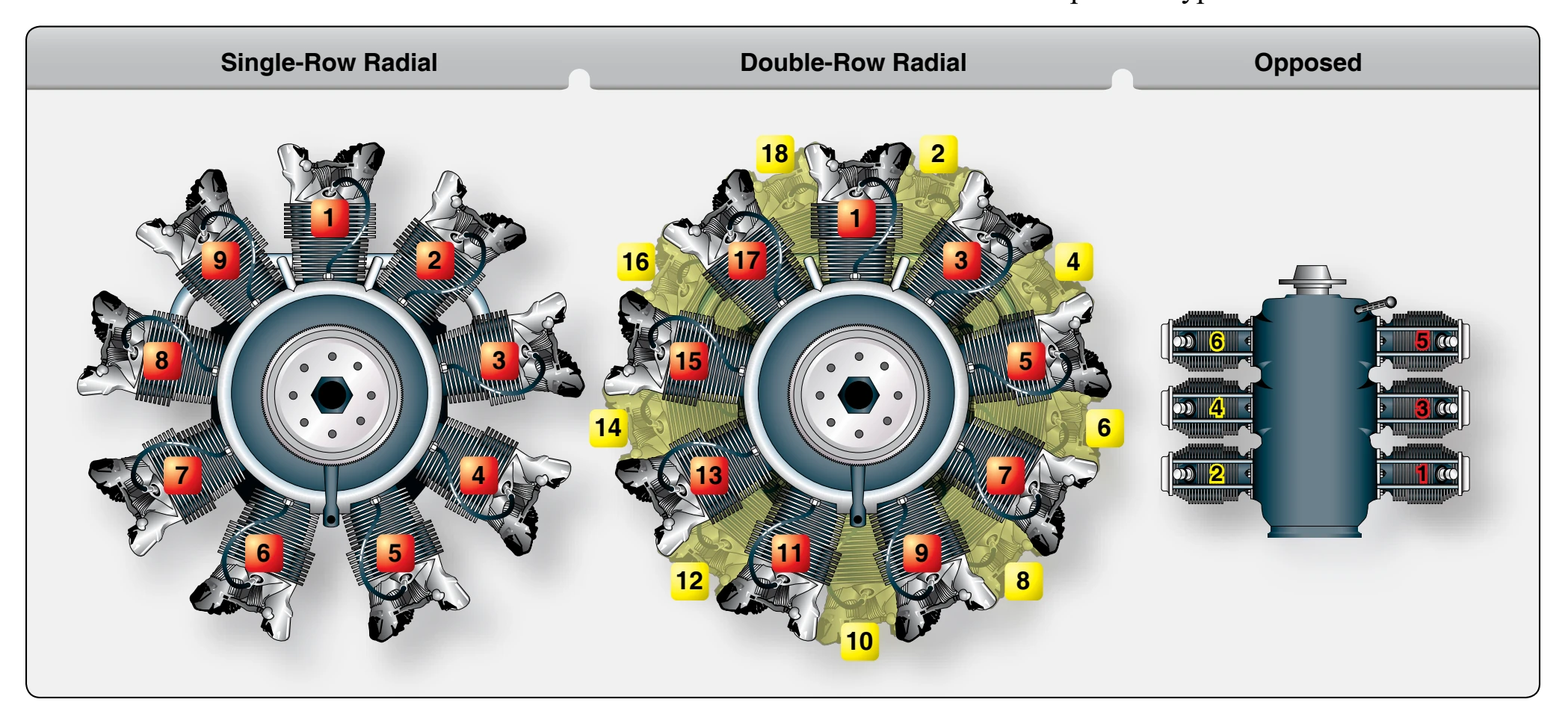
On a double-row radial engine, the firing order is somewhat complicated. The firing order is arranged with the firing impulse occurring in a cylinder in one row and then in a cylinder in the other row; therefore, two cylinders in the same row never fire in succession.
An easy method for computing the firing order of a 14-cylinder, double-row radial engine is to start with any number from 1 to 14 and add 9 or subtract 5 (these are called the firing order numbers), whichever gives an answer between 1 and 14, inclusive. For example, starting with 8, 9 cannot be added since the answer would then be more than 14; therefore, subtract 5 from 8 to get 3, add 9 to 3 to get 12, subtract 5 from 12 to get 7, subtract 5 from 7 to get 2, and so on.
The firing order numbers of an 18-cylinder, double-row radial engine are 11 and 7; that is, begin with any number from 1 to 18 and add 11 or subtract 7. For example, beginning with 1, add 11 to get 12; 11 cannot be added to 12 because the total would be more than 18, so subtract 7 to get 5, add 11 to 5 to get 16, subtract 7 from 16 to get 9, subtract 7 from 9 to get 2, add 11 to 2 to get 13, and continue this process for 18 cylinders.
Valves
The air-fuel mixture enters the cylinders through the intake valve ports, and burned gases are expelled through the exhaust valve ports. The head of each valve opens and closes these cylinder ports. The valves used in aircraft engines are the conventional poppet type. The valves are also typed by their shape and are called either mushroom or tulip because of their resemblance to the shape of these plants. Figure 1-20
Valve Construction
The valves in the cylinders of an aircraft engine are subjected to high temperatures, corrosion, and operating stresses; thus, the metal alloy in the valves must be able to resist all these factors. Because intake valves operate at lower temperatures than exhaust valves, they can be made of chromic-nickel steel. Exhaust valves are usually made of nichrome, silchrome, or cobalt-chromium steel because these materials are much more heat resistant.
The valve head has a ground face that forms a seal against the ground valve seat in the cylinder head when the valve is closed. The face of the valve is usually ground to an angle of either 30° or 45°. In some engines, the intake-valve face is ground to an angle of 30°, and the exhaust-valve face is ground to a 45° angle. Valve faces are often made more durable by the application of a material called stellite. About 1⁄ inch of this alloy is welded to the valve face and ground 16 to the correct angle. Stellite is resistant to high-temperature corrosion and also withstands the shock and wear associated with valve operation. Some engine manufacturers use a nichrome facing on the valves. This serves the same purpose as the stellite material.
The valve stem acts as a pilot for the valve head and rides in
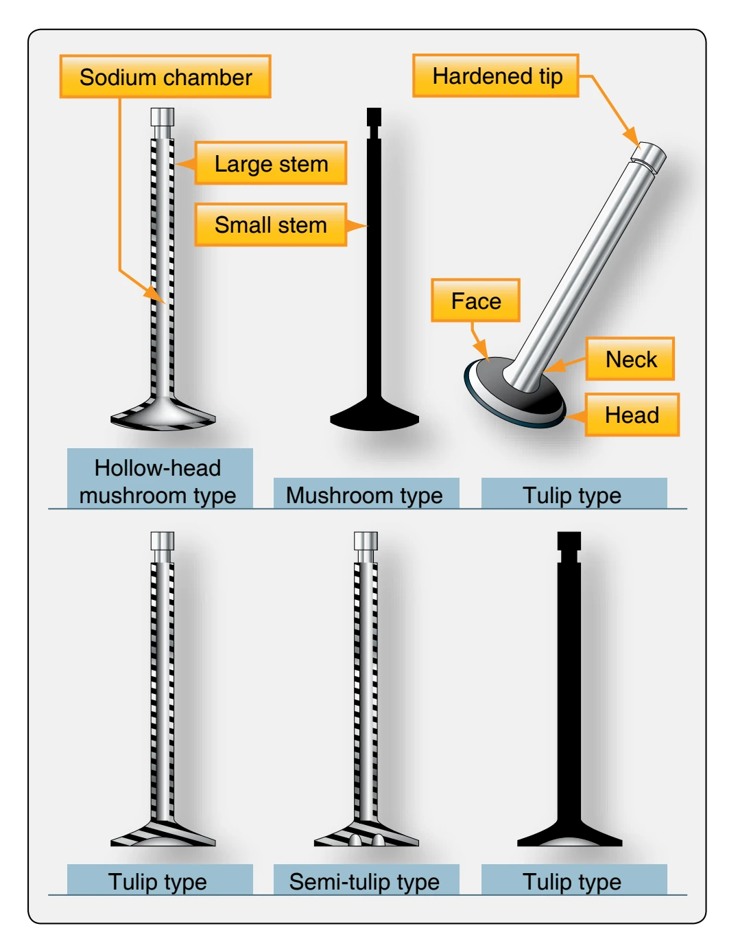
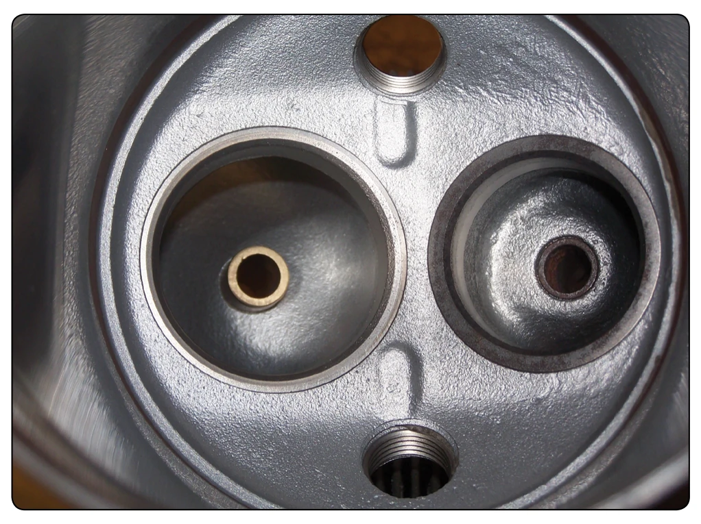
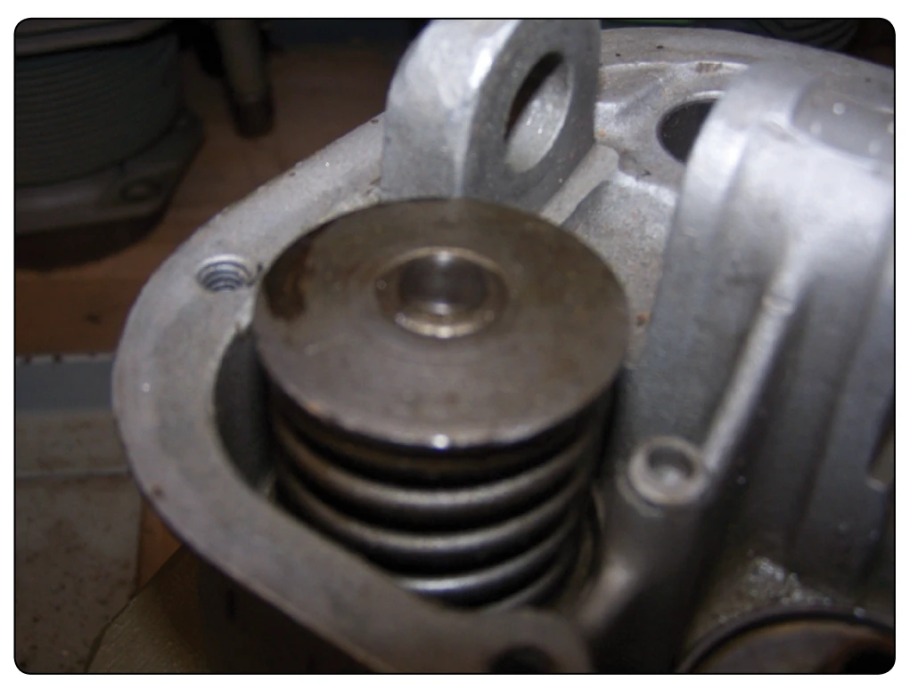
the valve guide installed in the cylinder head for this purpose. [Figure 1-21] The valve stem is surface hardened to resist wear. The neck is the part that forms the junction between the head and the stem. The tip of the valve is hardened to withstand the hammering of the valve rocker arm as it opens the valve. A machined groove on the stem near the tip receives the split-ring stem keys. These stem keys form a lock ring to hold the valve spring retaining washer in place. [Figure 1-22]
Some intake and exhaust valve stems are hollow and partially filled with metallic sodium. This material is used because it is an excellent heat conductor. The sodium melts at approximately 208 °F and the reciprocating motion of the valve circulates the liquid sodium, allowing it to carry away heat from the valve head to the valve stem where it is dissipated through the valve guide to the cylinder head and the cooling fins. Thus, the operating temperature of the valve may be reduced as much as 300° to 400 °F. Under no circumstances should a sodium-filled valve be cut open
or subjected to treatment which may cause it to rupture. Exposure of the sodium in these valves to the outside air results in fire or explosion with possible personal injury.
The most commonly used intake valves have solid stems, and the head is either flat or tulip shaped. Intake valves for low-power engines are usually flat headed. In some engines, the intake valve may be the tulip type and have a smaller stem than the exhaust valve or it may be similar to the exhaust valve but have a solid stem and head. Although these valves are similar, they are not interchangeable since the faces of the valves are constructed of different material. The intake valve usually has a flat milled on the tip to identify it.
Valve Operating Mechanism
For a reciprocating engine to operate properly, each valve must open at the proper time, stay open for the required length of time, and close at the proper time. Intake valves are opened just before the piston reaches top dead center, and exhaust valves remain open after top dead center. At a particular instant, therefore, both valves are open at the same time (end of the exhaust stroke and beginning of the intake stroke). This valve overlap permits better volumetric efficiency and lowers the cylinder operating temperature. This timing of the valves is controlled by the valve-operating mechanism and is referred to as the valve timing.