
Chapter 1
Aircraft Engines
The opposed-type engine has two banks of cylinders directly opposite each other with a crankshaft in the center. [Figure 1-1] The pistons of both cylinder banks are connected to the single crankshaft. Although the engine can be either liquid cooled or air cooled, the air-cooled version is used predominantly in aviation. It is generally mounted with the cylinders in a horizontal position. The opposed-type engine has a low weight-to-horsepower ratio, and its narrow silhouette makes it ideal for horizontal installation on the aircraft wings (twin engine applications). Another advantage is its low vibration characteristics.
V-Type Engines
In V-type engines, the cylinders are arranged in two inline banks generally set 60° apart. Most of the engines have 12 cylinders, which are either liquid cooled or air cooled. The engines are designated by a V followed by a dash and the piston displacement in cubic inches. For example, V-1710. This type of engine was used mostly during the Second World War and its use is mostly limited to older aircraft.
Radial Engines
The radial engine consists of a row, or rows, of cylinders arranged radially about a central crankcase. [Figure 1-2] This type of engine has proven to be very rugged and dependable. The number of cylinders which make up a row may be three,

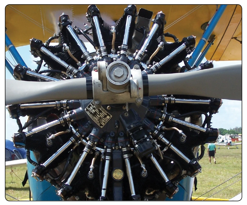
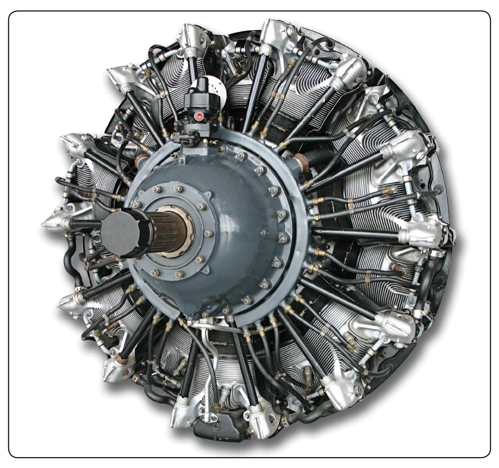
five, seven, or nine. Some radial engines have two rows of seven or nine cylinders arranged radially about the crankcase, one in front of the other. These are called double-row radials. [Figure 1-3] One type of radial engine has four rows of cylinders with seven cylinders in each row for a total of 28 cylinders. Radial engines are still used in some older cargo airplanes, war birds, and crop spray airplanes. Although many of these engines still exist, their use is limited. The single-row, nine-cylinder radial engine is of relatively simple construction, having a one-piece nose and a two-section main crankcase. The larger twin-row engines are of slightly more complex construction than the single row engines. For example, the crankcase of the Wright R-3350 engine is composed of the crankcase front section, four crankcase main sections (front main, front center, rear center, and
rear main), rear cam and tappet housing, supercharger front housing, supercharger rear housing, and supercharger rear housing cover. Pratt and Whitney engines of comparable size incorporate the same basic sections, although the construction and the nomenclature differ considerably.
Reciprocating Engines
Design & Construction
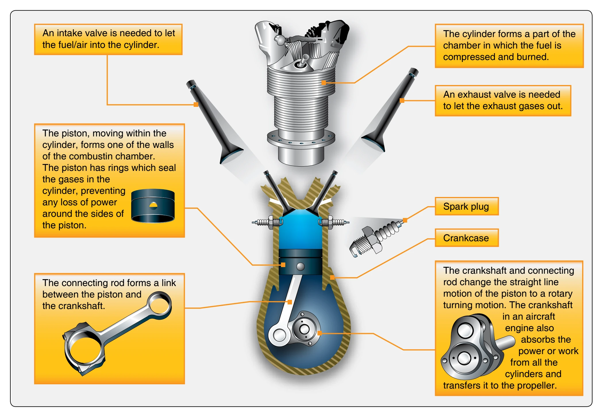
The basic major components of a reciprocating engine are the crankcase, cylinders, pistons, connecting rods, valves, valve-operating mechanism, and crankshaft. In the head of each cylinder are the valves and spark plugs. One of the valves is in a passage leading from the induction system; the other is in a passage leading to the exhaust system. Inside each cylinder is a movable piston connected to a crankshaft by a connecting rod. Figure 1-4 illustrates the basic parts of a reciprocating engine.
Crankcase Section
The foundation of an engine is the crankcase. It contains the bearings and bearing supports in which the crankshaft revolves. Besides supporting itself, the crankcase must provide a tight enclosure for the lubricating oil and must support various external and internal mechanisms of the engine. It also provides support for attachment of the cylinder assemblies, and the powerplant to the aircraft. It must be sufficiently rigid and strong to prevent misalignment of the crankshaft and its bearings. Cast or forged aluminum alloy is generally used for crankcase construction because it is light and strong. The crankcase is subjected to many variations of mechanical loads and other forces. Since the cylinders are fastened to the crankcase, the tremendous forces placed on the cylinder tend to pull the cylinder off the crankcase. The unbalanced centrifugal and inertia forces of the crankshaft acting through the main bearings subject the crankcase to bending moments which change continuously in direction and magnitude. The crankcase must have sufficient stiffness to withstand these bending moments without major deflections. [Figure 1-5]
If the engine is equipped with a propeller reduction gear, the front or drive end is subjected to additional forces. In addition to the thrust forces developed by the propeller under high power output, there are severe centrifugal and gyroscopic forces applied to the crankcase due to sudden changes in the direction of flight, such as those occurring during maneuvers of the airplane. Gyroscopic forces are particularly severe when a heavy propeller is installed. To absorb centrifugal loads, a large centrifugal bearing is used in the nose section.
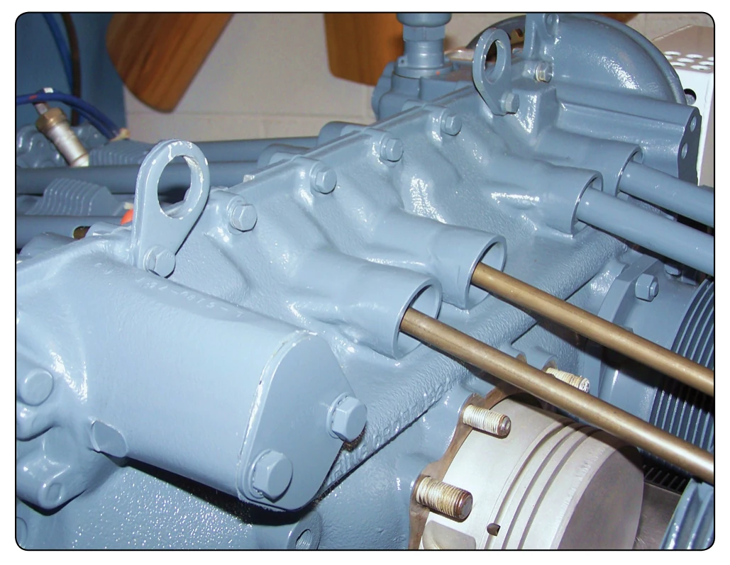
The shape of the nose or front of the crankcase section varies considerably. In general, it is either tapered or round. Depending upon the type of reciprocating engine, the nose or front area of the crankcase varies somewhat. If the propeller is driven directly by the crankshaft, less area is needed for this component of the engine. The crankcases used on engines having opposed or inline cylinder arrangements vary in form for the different types of engines, but in general they are approximately cylindrical. One or more sides are surfaced to serve as a base to which the cylinders are attached by means of cap screws, bolts, or studs. These accurately machined surfaces are frequently referred to as cylinder pads.
If the propeller is driven by reduction gearing (gears that slow down the speed of the propeller less than the engine), more area is required to house the reduction gears. A tapered nose section is used quite frequently on direct-drive, low-powered engines, because extra space is not required to house the propeller reduction gears. Crankcase nose sections are usually cast of either aluminum alloy or magnesium. The crankcase nose section on engines that develop from 1,000 to 2,500 hp is usually larger to house reduction gears and sometimes ribbed to get as much strength as possible.