
Chapter 1
Aircraft Engines
The governor is used to control propeller speed and blade angle. The mounting of the propeller governor varies. On some engines, it is located on the rear section, although this complicates the installation, especially if the propeller is operated or controlled by oil pressure, because of the distance between the governor and propeller. Where hydraulically operated propellers are used, it is good practice to mount the governor on the nose section as close to the propeller as possible to reduce the length of the oil passages. The governor is then driven either from gear teeth on the periphery of the bell gear or by some other suitable means. This basic arrangement is also used for turboprops.
On some of the larger radial engines, a small chamber is located on the bottom of the nose section to collect the oil. This is called the nose section oil sump. Since the nose section transmits many varied forces to the main crankcase or power section, it must be secured properly to transmit the loads efficiently.
The machined surfaces on which the cylinders are mounted are called cylinder pads. They are provided with a suitable means of retaining or fastening the cylinders to the crankcase. The general practice in securing the cylinder flange to the pad is to mount studs in threaded holes in the crankcase. The inner portion of the cylinder pads are sometimes chamfered or tapered to permit the installation of a large rubber O-ring around the cylinder skirt, which effectively seals the joint between the cylinder and the crankcase pads against oil leakage.
Because oil is thrown about the crankcase, especially on inverted inline and radial-type engines, the cylinder skirts extend a considerable distance into the crankcase sections to reduce the flow of oil into the inverted cylinders. The piston and ring assemblies must be arranged so that they throw out the oil splashed directly into them.
Mounting lugs are spaced about the periphery of the rear of the crankcase or the diffuser section of a radial engine. These are used to attach the engine assembly to the engine mount or framework provided for attaching the powerplant to the fuselage of single-engine aircraft or to the wing nacelle structure of multiengine aircraft. The mounting lugs may be either integral with the crankcase or diffuser section or detachable, as in the case of flexible or dynamic engine mounts.
The mounting arrangement supports the entire powerplant including the propeller, and therefore is designed to provide ample strength for rapid maneuvers or other loadings. Because of the elongation and contraction of the cylinders, the intake pipes which carry the mixture from the diffuser chamber through the intake valve ports are arranged to provide a slip joint which must be leak proof. The atmospheric pressure on the outside of the case of an un-supercharged engine is higher than on the inside, especially when the engine is operating at idling speed. If the engine is equipped with a supercharger and operated at full throttle, the pressure is considerably higher on the inside than on the outside of the case. If the slip joint connection has a slight leakage, the engine may idle fast due to a slight leaning of the mixture. If the leak is quite large, it may not idle at all. At open throttle, a small leak probably would not be noticeable in operation of the engine, but the slight leaning of the air-fuel mixture might cause detonation or damage to the valves and valve seats. On some radial engines, the intake pipe has considerable length and on some inline engines, the intake pipe is at right angles to the cylinders. In these cases, flexibility of the intake pipe or its arrangement eliminates the need for a slip joint. In any case, the engine induction system must be arranged so that it does not leak air and change the desired air-fuel ratio.
Accessory Section
The accessory (rear) section usually is of cast construction and the material may be either aluminum alloy, which is used most widely, or magnesium, which has been used to some extent. On some engines, it is cast in one piece and provided with means for mounting the accessories, such as magnetos, carburetors, fuel, oil, vacuum pumps, starter, generator, tachometer drive, etc., in the various locations required to facilitate accessibility. Other adaptations consist of an aluminum alloy casting and a separate cast magnesium cover plate on which the accessory mounts are arranged. Accessory drive shafts are mounted in suitable drive arrangements that are carried out to the accessory mounting pads. In this manner, the various gear ratios can be arranged to give the proper drive speed to magnetos, pumps, and other accessories to obtain correct timing or functioning.
Accessory Gear Trains
Gear trains, containing both spur- and bevel-type gears, are used in the different types of engines for driving engine components and accessories. Spur-type gears are generally used to drive the heavier loaded accessories or those requiring the least play or backlash in the gear train. Bevel gears permit angular location of short stub shafts leading to the various accessory mounting pads. On opposed, reciprocating engines, the accessory gear trains are usually simple arrangements. Many of these engines use simple gear trains to drive the engine’s accessories at the proper speeds.
Crankshafts
The crankshaft is carried in a position parallel to the longitudinal axis of the crankcase and is generally supported by a main bearing between each throw. The crankshaft main bearings must be supported rigidly in the crankcase. This usually is accomplished by means of transverse webs in the crankcase, one for each main bearing. The webs form an integral part of the structure and, in addition to supporting the main bearings, add to the strength of the entire case.
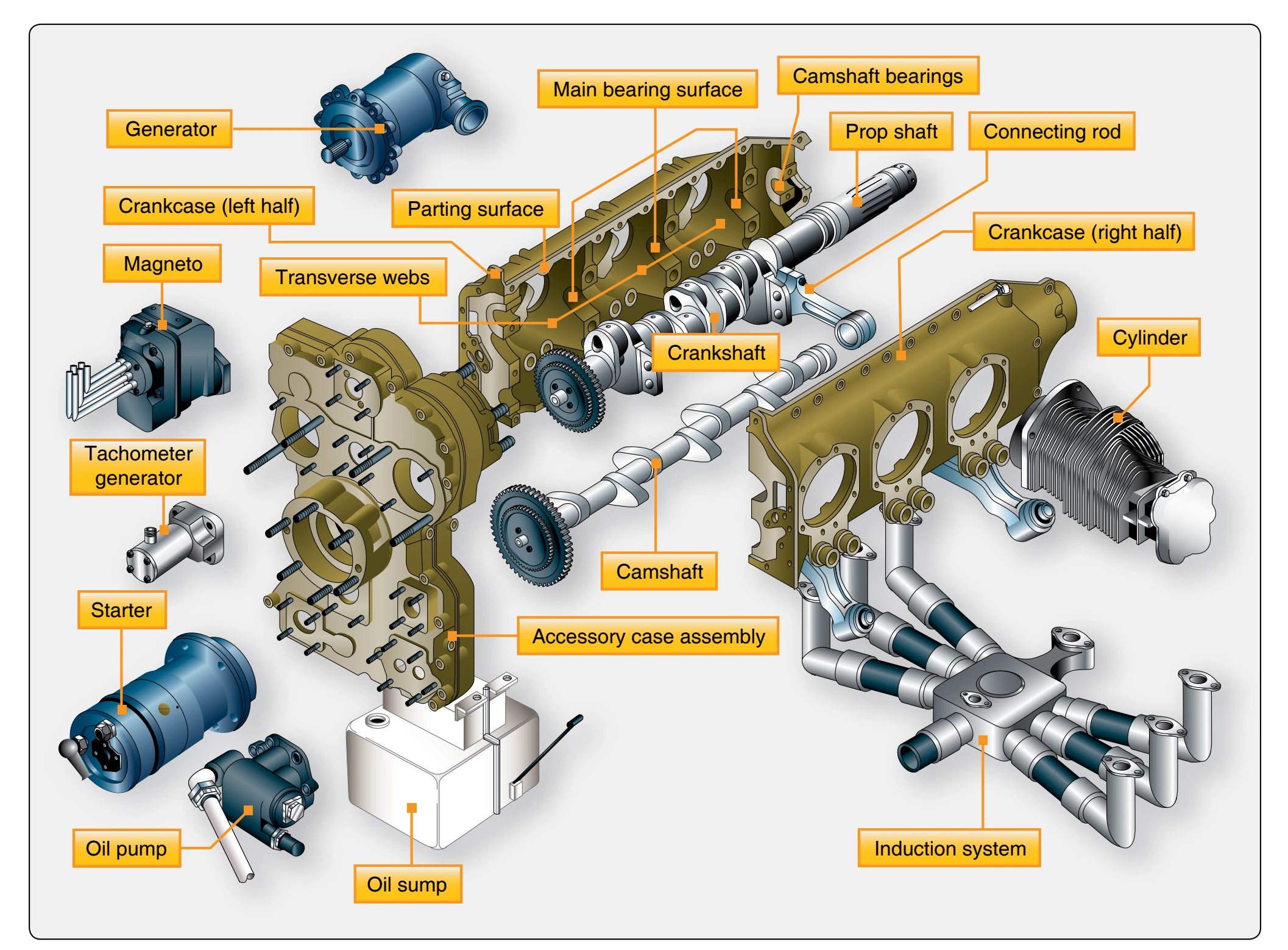
The crankcase is divided into two sections in a longitudinal plane. This division may be in the plane of the crankshaft so that one-half of the main bearing (and sometimes camshaft bearings) are carried in one section of the case and the other half in the opposite section. [Figure 1-6] Another method is to divide the case in such a manner that the main bearings are secured to only one section of the case on which the cylinders are attached, thereby providing means of removing a section of the crankcase for inspection without disturbing the bearing adjustment.
The crankshaft is the backbone of the reciprocating engine. It is subjected to most of the forces developed by the engine. Its main purpose is to transform the reciprocating motion of the piston and connecting rod into rotary motion for rotation of the propeller. The crankshaft, as the name implies, is a shaft composed of one or more cranks located at specified points along its length. The cranks, or throws, are formed by forging offsets into a shaft before it is machined. Since crankshafts must be very strong, they generally are forged from a very strong alloy, such as chromium-nickel-molybdenum steel.
A crankshaft may be of single-piece or multipiece construction. Figure 1-7 shows two representative types of solid crankshafts used in aircraft engines. The four-throw construction may be used either on four-cylinder horizontal opposed or four-cylinder inline engines. The six-throw shaft is used on six-cylinder inline engines, 12-cylinder V-type engines, and six-cylinder opposed engines. Crankshafts of radial engines may be the single-throw, two-throw, or four-throw type, depending on whether the engine is the single-row, twin-row, or four-row type. A single-throw radial engine crankshaft is shown in Figure 1-8. No matter how many throws it may have, each crankshaft has three main parts—a journal, crankpin, and crank cheek. Flyweights and dampers, although not a true part of a crankshaft, are usually attached to it to reduce engine vibration.
The journal is supported by, and rotates in, a main bearing. It serves as the center of rotation of the crankshaft. It is surfacehardened to reduce wear. The crankpin is the section to which the connecting rod is attached. It is off-center from the main journals and is often called the throw. Two crank cheeks and a crankpin make a throw. When a force is applied to the crankpin in any direction other than parallel or perpendicular to and through the center line of the crankshaft, it causes the crankshaft to rotate. The outer surface is hardened by nitriding to increase its resistance to wear and to provide the required bearing surface. The crankpin is usually hollow. This reduces the total weight of the crankshaft and provides a passage for the transfer of lubricating oil. On early engines, the hollow crankpin also served as a chamber for collecting sludge, carbon deposits, and other foreign material. Centrifugal force threw these substances to the outside of the chamber and kept them from reaching the connecting-rod bearing surface. Due to the use of ashless dispersant oils, newer engines no longer use sludge chambers. On some engines, a passage is drilled in the crank cheek to allow oil from the hollow crankshaft to be sprayed on the cylinder walls. The crank cheek connects the crankpin to the main journal. In some designs, the cheek extends beyond the journal and carries a flyweight to balance the crankshaft. The crank cheek must be of sturdy construction to obtain the required rigidity between the crankpin and the journal.
In all cases, the type of crankshaft and the number of crankpins must correspond with the cylinder arrangement of the engine. The position of the cranks on the crankshaft in relation to the other cranks of the same shaft is expressed in degrees.
The simplest crankshaft is the single-throw or 360° type. This type is used in a single-row radial engine. It can be constructed in one or two pieces. Two main bearings (one on each end) are provided when this type of crankshaft is used. The double-throw or 180° crankshaft is used on doublerow radial engines. In the radial-type engine, one throw is provided for each row of cylinders.