
Chapter 1
Aircraft Engines
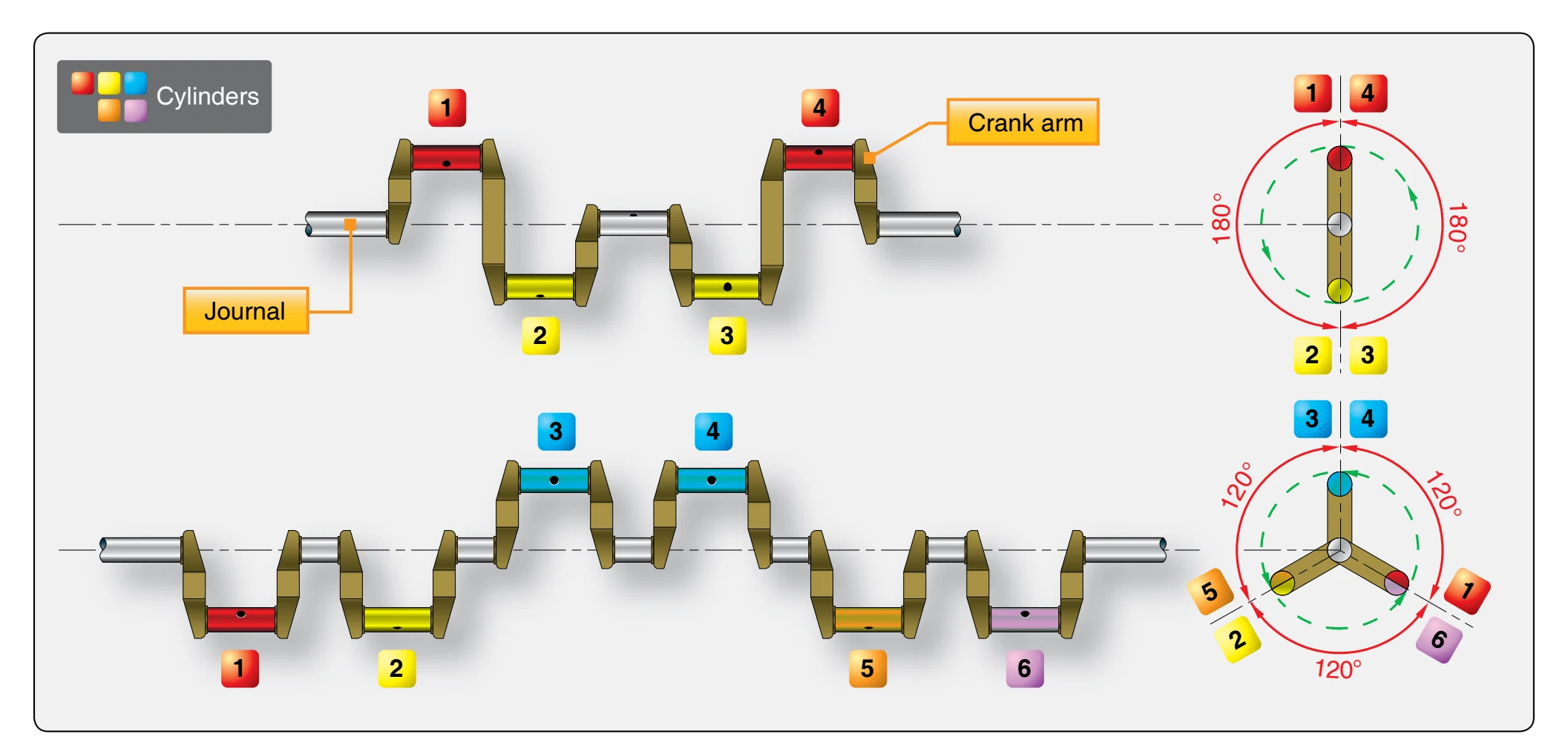
Excessive vibration in an engine not only results in fatigue failure of the metal structures, but also causes the moving parts to wear rapidly. In some instances, excessive vibration is caused by a crankshaft that is not balanced. Crankshafts are balanced for static balance and dynamic balance. A crankshaft is statically balanced when the weight of the entire assembly of crankpins, crank cheeks, and flyweights is balanced around the axis of rotation. When checked for static balance, it is placed on two knife edges. If the shaft tends to turn toward any one position during the test, it is out of static balance. Any engine to be overhauled completely should receive a runout check of its crankshaft as a first step. Any question concerning crankshaft replacement is resolved at this time since a shaft whose runout is beyond limits must be replaced.
Dynamic Dampers
A crankshaft is dynamically balanced when all the forces created by crankshaft rotation and power impulses are balanced within themselves so that little or no vibration is produced when the engine is operating. To reduce vibration to a minimum during engine operation, dynamic dampers are incorporated on the crankshaft. A dynamic damper is merely a pendulum that is fastened to the crankshaft so that it is free to move in a small arc. It is incorporated in the flyweight assembly. Some crankshafts incorporate two or more of these assemblies, each being attached to a different crank cheek. The distance the pendulum moves and, thus, its vibrating
frequency corresponds to the frequency of the power impulses of the engine. When the vibration frequency of the crankshaft occurs, the pendulum oscillates out of time with the crankshaft vibration, thus reducing vibration to a minimum.
The construction of the dynamic damper used in one engine consists of a movable slotted-steel flyweight attached to the
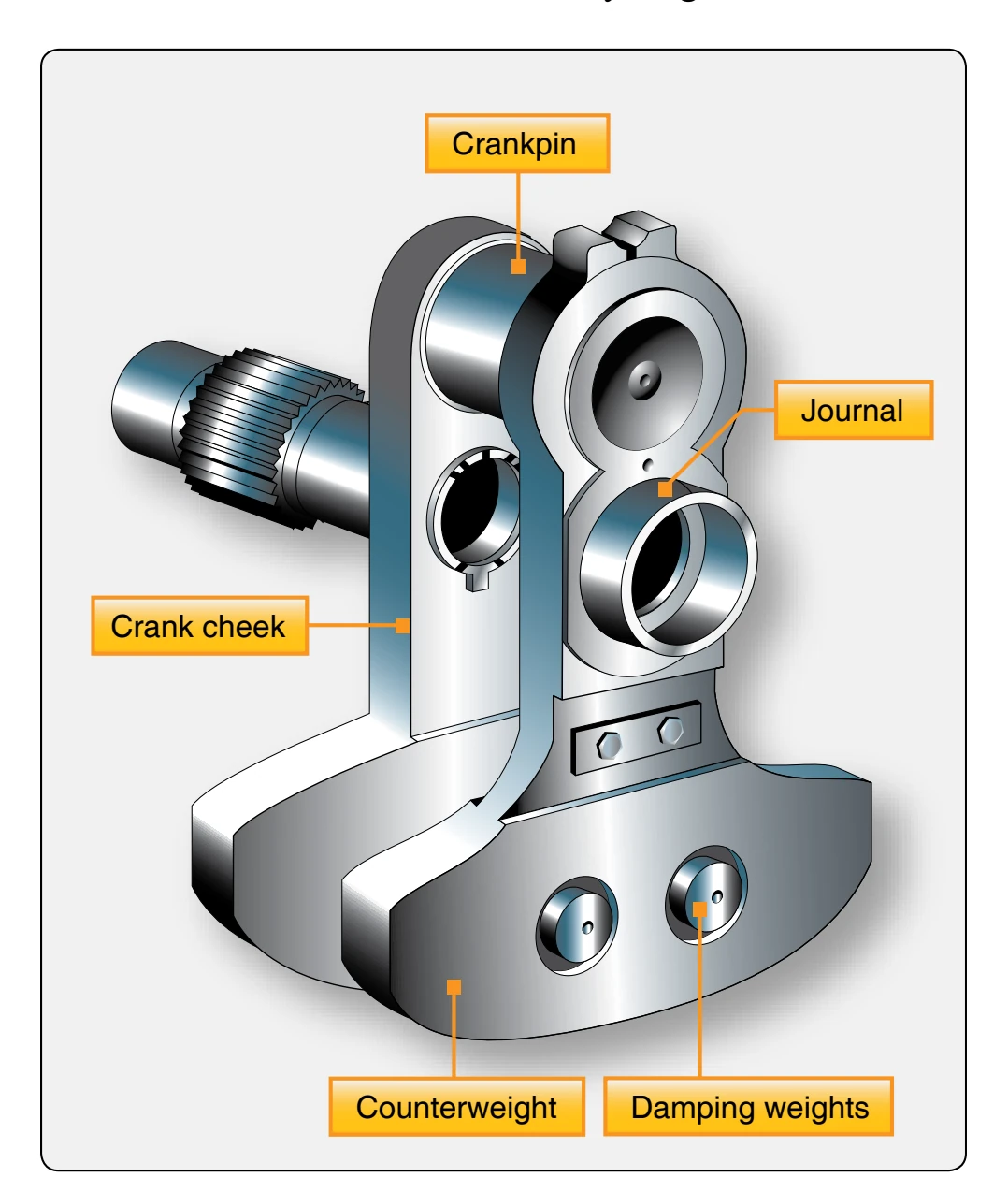
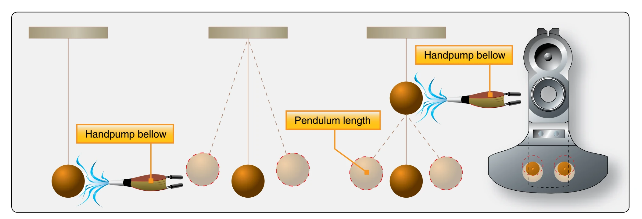
crank cheek. Two spool-shaped steel pins extend into the slot and pass through oversized holes in the flyweight and crank cheek. The difference in the diameter between the pins and the holes provides a pendulum effect. An analogy of the functioning of a dynamic damper is shown in Figure 1-9.
Connecting Rods
The connecting rod is the link that transmits forces between the piston and the crankshaft. [Figure 1-10] Connecting rods must be strong enough to remain rigid under load and yet be light enough to reduce the inertia forces that are produced when the rod and piston stop, change direction, and start again at the end of each stroke.
There are four types of connecting-rod assemblies [Figure 1-11]:
- Plain.
- Fork and blade.
- Master and articulated.
- Split-type.
Master-and-Articulated Rod Assembly
The master-and-articulated rod assembly is commonly used in radial engines. In a radial engine, the piston in one cylinder in each row is connected to the crankshaft by a master rod. All other pistons in the row are connected to the master rod by articulated rods. In an 18-cylinder engine, which has two rows of cylinders, there are two master rods and 16 articulated rods. The articulated rods are constructed of forged steel alloy in either the I- or H-shape, denoting the cross-sectional shape. Bronze bushings are pressed into the
bores in each end of the articulated rod to provide knucklepin and piston-pin bearings.
The master rod serves as the connecting link between the piston pin and the crankpin. The crankpin end, or the big end, contains the crankpin or master rod bearing. Flanges around the big end provide for the attachment of the articulated rods. The articulated rods are attached to the master rod by knuckle pins, which are pressed into holes in the master rod flanges during assembly. A plain bearing, usually called a piston-pin bushing, is installed in the piston end of the master rod to receive the piston pin.
When a crankshaft of the split-spline or split-clamp type is employed, a one-piece master rod is used. The master and articulated rods are assembled and then installed on the crankpin; the crankshaft sections are then joined together. In engines that use the one-piece type of crankshaft, the big end of the master rod is split, as is the master rod bearing. The main part of the master rod is installed on the crankpin; then the bearing cap is set in place and bolted to the master rod. The centers of the knuckle pins do not coincide with the center of the crankpin. Thus, while the crankpin center describes a true circle for each revolution of the crankshaft, the centers of the knuckle pins describe an elliptical path. [Figure 1-12] The elliptical paths are symmetrical about a center line through the master rod cylinder. It can be seen that the major diameters of the ellipses are not the same. Thus, the link rods have varying degrees of angularity relative to the center of the crank throw.
Because of the varying angularity of the link rods and the elliptical motion of the knuckle pins, all pistons do not move an equal amount in each cylinder for a given number of degrees of crank throw movement. This variation in piston position between cylinders can have considerable effect on engine operation. To minimize the effect of these factors on valve and ignition timing, the knuckle pin holes in the master rod flange are not equidistant from the center of the crankpin, thereby offsetting to an extent the effect of the link rod angularity.
Another method of minimizing the adverse effects on engine operation is to use a compensated magneto. In this magneto the breaker cam has a number of lobes equal to the number of cylinders on the engine. To compensate for the variation in piston position due to link rod angularity, the breaker cam lobes are ground with uneven spacing. This allows the breaker contacts to open when the piston is in the correct firing position. This is further outlined during the discussion on ignition timing in Chapter 4, Engine Ignition & Electrical Systems.