
Chapter 1
Aircraft Engines
Turboshaft Engines
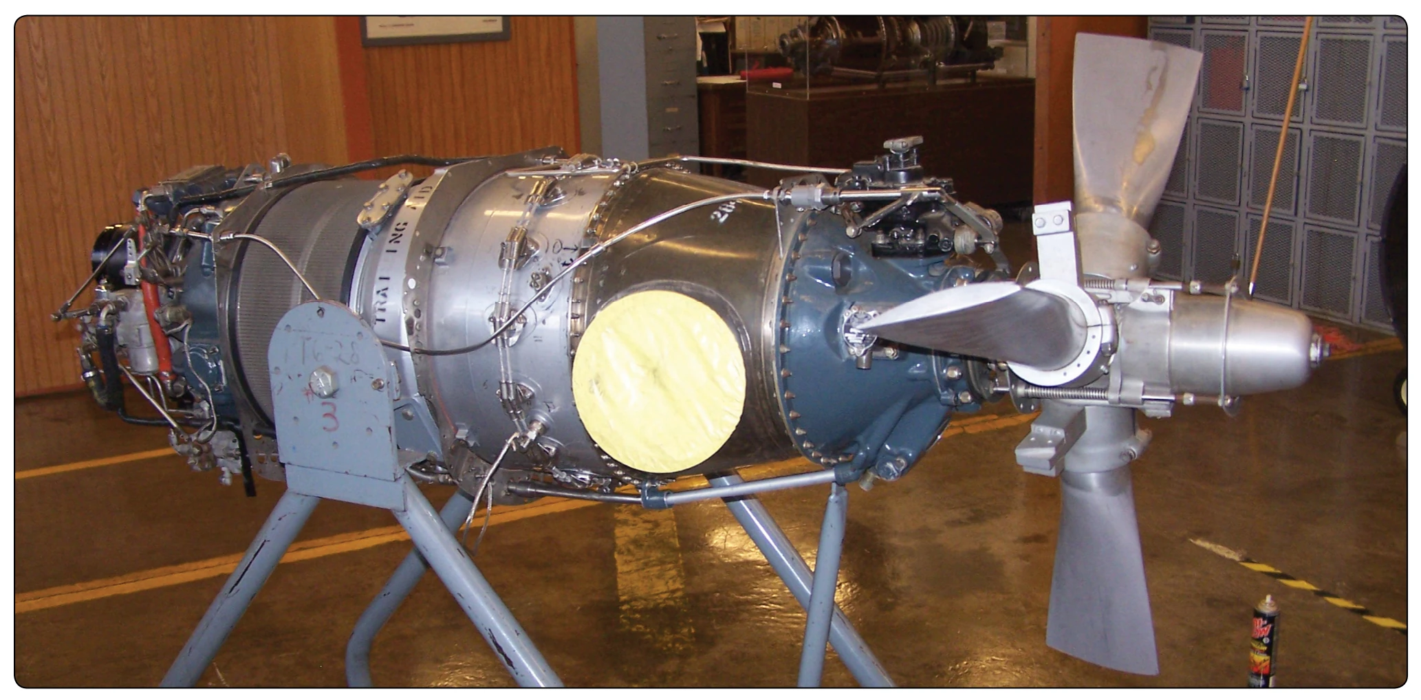
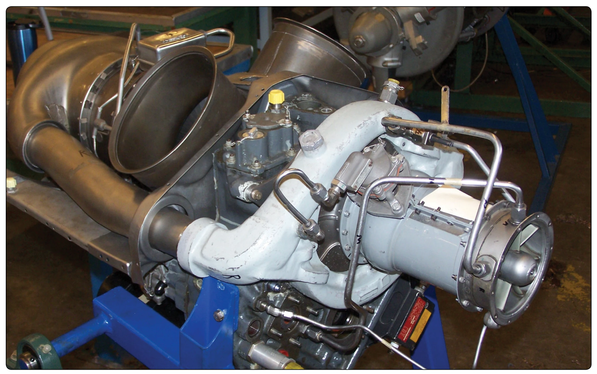
A gas-turbine engine that delivers power through a shaft to operate something other than a propeller is referred to as a turboshaft engine. [Figure 1-79] The output shaft may be coupled directly to the engine turbine, or the shaft may be driven by a turbine of its own (free turbine) located in the exhaust stream. As mentioned with the turboprop, the free turbine rotates independently. This principle is used extensively in current production of turboshaft engines. The turboshaft engine’s output is measured in horsepower instead of thrust because the power output is a turning shaft.
Turbofan Engines
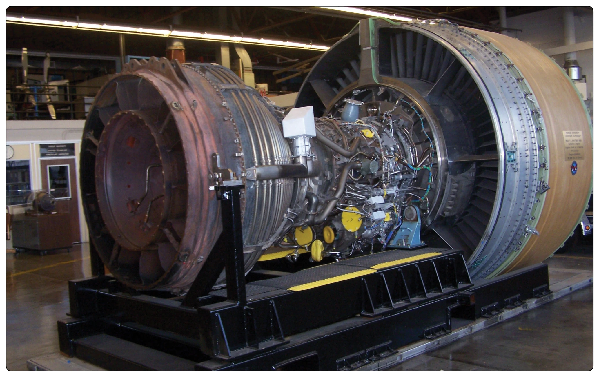
The turbofan gas turbine engine is, in principle, the same as a turboprop, except that the propeller is replaced by a ductenclosed axial-flow fan. [Figure 1-80] The fan can be a part of the first-stage compressor blades or can be mounted as a separate set of fan blades. The blades are mounted forward of the compressor.
The general principle of the fan engine is to convert more of the fuel energy into pressure. With more of the energy
converted to pressure, a greater product of pressure times area can be achieved. One of the major advantages is turbofan production of this additional thrust without increasing fuel flow. The end result is fuel economy with the consequent increase in range. Because more of the fuel energy is turned into pressure in the turbofan engine, additional stages must be added in the turbine section to provide the power to drive the fan. This means there is less energy left over and less thrust from the core exhaust gases. Also, in a mixed-exhaust nozzle (where fan air and core air mix in a common nozzle before entering ambient conditions) the exhaust nozzle must be larger in area. The result is that the fan develops most of the thrust. The thrust produced by the fan more than makes up for the decrease in thrust of the core (gas generator) of the engine. Depending on the fan design and bypass ratio, it produces 80 percent of the turbofan engine’s total thrust.
Two different exhaust nozzle designs are used with turbofan engines. The air leaving the fan can be ducted overboard by a separate fan nozzle [Figure 1-43], or it can be ducted along the outer case of the basic engine to be discharged through the mixed nozzle (core and fan exhaust together). The fan air is either mixed with the exhaust gases before it is discharged (mixed or common nozzle), or it passes directly to the atmosphere without prior mixing (separate nozzle). Turbofans are the most widely used gas turbine engine for air transport aircraft. The turbofan is a compromise between the good operating efficiency and high thrust capability of a turboprop and the high speed, high altitude capability of a turbojet.
Turbine Engine Operating Principles
The principle used by a gas turbine engine as it provides force to move an airplane is based on Newton’s Third Law. This law states that for every action there is an equal and opposite reaction; therefore, if the engine accelerates a mass of air (action), it applies a force on the aircraft (reaction). The turbofan generates thrust by giving a relatively slower acceleration to a large quantity of air. The old pure turbojet engine achieves thrust by imparting greater acceleration to a smaller quantity of air. This was its main problem with fuel consumption and noise.
The mass of air is accelerated within the engine by the use of a continuous-flow cycle. Ambient air enters the inlet diffuser where it is subjected to changes in temperature, pressure, and velocity due to ram effect. The compressor then increases pressure and temperature of the air mechanically. The air continues at constant pressure to the burner section where its temperature is increased by combustion of fuel. The energy is taken from the hot gas by expanding through a turbine which drives the compressor, and by expanding through an exhaust nozzle designed to discharge the exhaust gas at high velocity to produce thrust.
The high velocity gases from the engine may be considered continuous, imparting this force against the aircraft in which it is installed, thereby producing thrust. The formula for thrust can be derived from Newton’s second law, which states that force is proportional to the product of mass and acceleration. This law is expressed in the following formula:
Newton's second law
Linear form: F = M × A; F = force in pounds; M = mass in pounds per second; A = acceleration in feet per second
In the above formula, mass is similar to weight, but it is actually a different quantity. Mass refers to the quantity of matter, while weight refers to the pull of gravity on that quantity of matter. At sea level under standard conditions, 1 pound of mass has a weight of 1 pound. To calculate the acceleration of a given mass, the gravitational constant is used as a unit of comparison. The force of gravity is 32.2 feet per second squared (ft/sec2). This means that a free falling 1 pound object accelerates at the rate of 32.2 feet per second each second that gravity acts on it. Since the object mass weighs 1 pound, which is also the actual force imparted to it by gravity, it can be assumed that a force of 1 pound accelerates a 1 pound object at the rate of 32.2 ft/sec2.
Also, a force of 10 pound accelerates a mass of 10 pound at the rate of 32.2 ft/sec2. This is assuming there is no friction or other resistance to overcome. It is now apparent that the ratio of the force (in pounds) is to the mass (in pounds) as the acceleration in ft/sec2 is to 32.2. Using M to represent the mass in pounds, the formula may be expressed thus:
Force, mass, acceleration, and gravity
Linear form: F / M = A / G, or F = MA / G; F = force; M = mass; A = acceleration; G = gravity
In any formula involving work, the time factor must be considered. It is convenient to have all time factors in equivalent units (i.e., seconds, minutes, or hours). In calculating jet thrust, the term “pounds of air per second” is convenient, since the second is the same unit of time used for the force of gravity.