
Chapter 1
Aircraft Engines
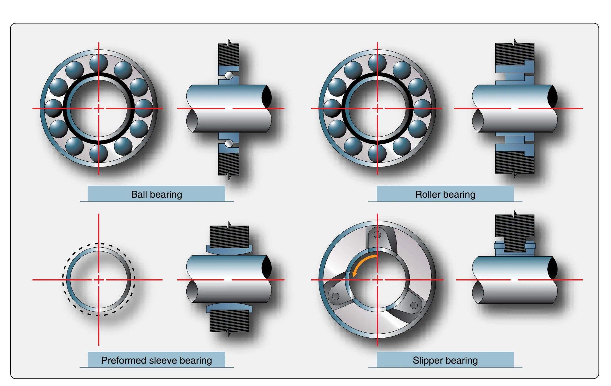
The main bearings have the critical function of supporting the main engine rotor. The number of bearings necessary for proper engine support is, for the most part, determined by the length and weight of the engine rotor. The length and weight are directly affected by the type of compressor used in the engine. Naturally, a two-spool compressor requires more bearing support. The minimum number of bearings required to support one shaft is one deep groove ball bearing (thrust and radial loads) and one straight roller bearing (radial load only). Sometimes, it is necessary to use more than one roller bearing if the shaft is subject to vibration or its length is excessive. The gas turbine rotors are supported by ball and roller bearings, which are antifriction bearings. [Figure 1-76] Many newer engines use hydraulic bearings, in which the outside race is surrounded by a thin film of oil. This reduces vibrations transmitted to the engine.
In general, antifriction bearings are preferred largely because they:
- Offer little rotational resistance,
- Facilitate precision alignment of rotating elements,
- Are relatively inexpensive,
- Are easily replaced,
- Withstand high momentary overloads,
- Are simple to cool, lubricate, and maintain,
- Accommodate both radial and axial loads, and
- Are relatively resistant to elevated temperatures.
The main disadvantages are their vulnerability to foreign matter and tendency to fail without appreciable warning. Usually the ball bearings are positioned on the compressor or turbine shaft so that they can absorb any axial (thrust) loads or radial loads. Because the roller bearings present a larger working surface, they are better equipped to support radial loads than thrust loads. Therefore, they are used primarily for this purpose. A typical ball or roller bearing assembly includes a bearing support housing, which must be strongly constructed and supported in order to carry the radial and axial loads of the rapidly rotating rotor. The bearing housing usually contains oil seals to prevent the oil leaking from its normal path of flow. It also delivers the oil to the bearing for its lubrication, usually through spray nozzles. The oil seals may be the labyrinth or thread (helical) type. These seals also may be pressurized to minimize oil leaking along the compressor shaft. The labyrinth seal is usually pressurized, but the helical seal depends solely on reverse threading to stop oil leakage. These two types of seals are very similar, differing only in thread size and the fact that the labyrinth seal is pressurized.
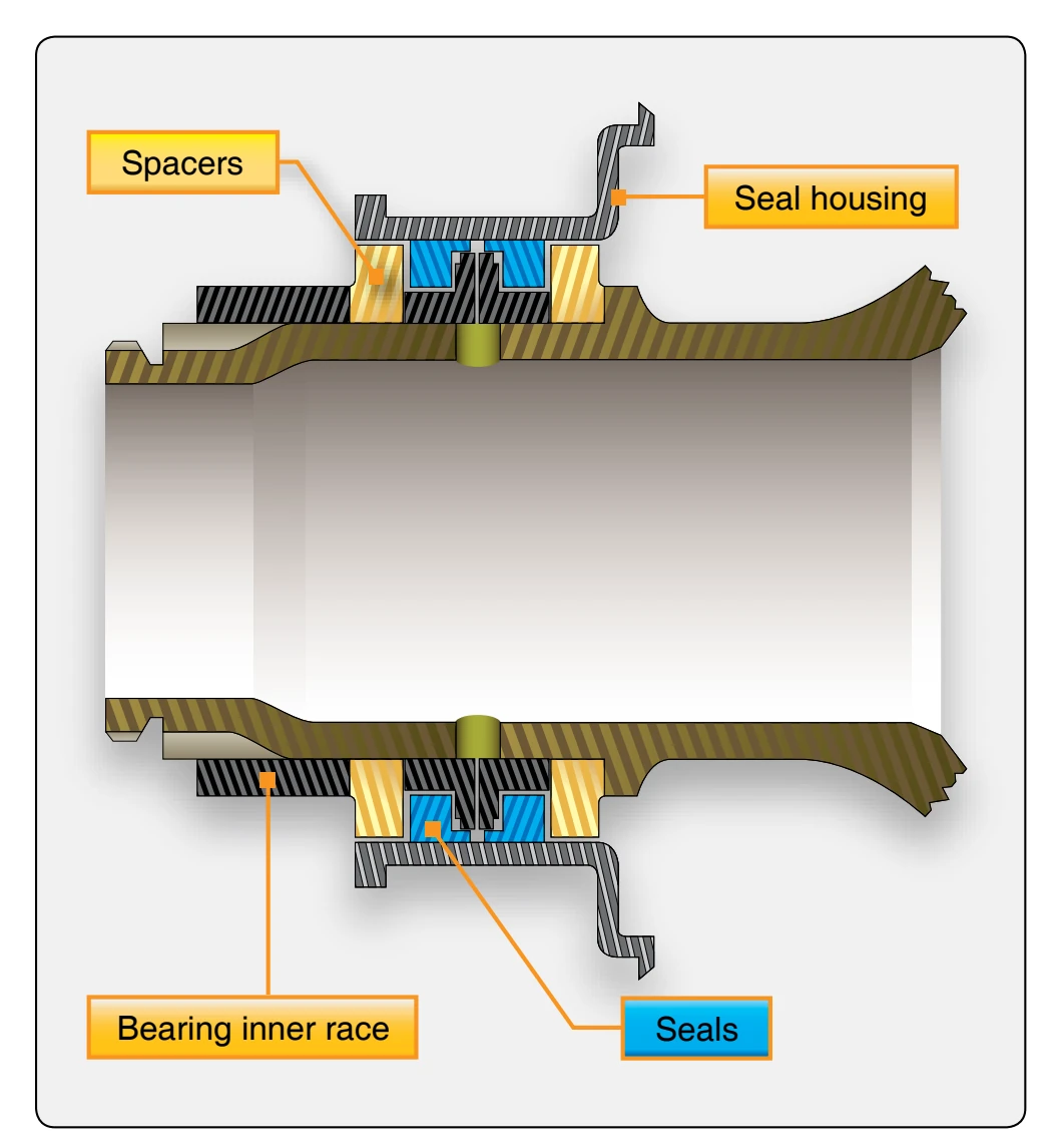
Another type of oil seal used on some of the later engines is the carbon seal. These seals are usually spring loaded and are similar in material and application to the carbon brushes
used in electrical motors. Carbon seals rest against a surface provided to create a sealed bearing cavity or void; thus, the oil is prevented from leaking out along the shaft into the compressor airflow or the turbine section. [Figure 1-77]
The ball or roller bearing is fitted into the bearing housing and may have a self-aligning feature. If a bearing is self-aligning, it is usually seated in a spherical ring. This allows the shaft a certain amount of radial movement without transmitting stress to the bearing inner race.
The bearing surface is usually provided by a machined journal on the appropriate shaft. The bearing is usually locked in position by a steel snap ring or other suitable locking device. The rotor shaft also provides the matching surface for the oil seals in the bearing housing. These machined surfaces are called lands and fit in rather close to the oil seal.
Turboprop Engines
The turbopropeller (turboprop) engine is a combination of a gas turbine engine, reduction gear box, and a propeller. [Figure 1-78] Turboprops are basically gas turbine engines that have a compressor, combustion chamber(s), turbine, and an exhaust nozzle (gas generator), all of which operate in the same manner as any other gas engine. However, the difference is that the turbine in the turboprop engine usually has extra stages to extract energy to drive the propeller. In addition to operating the compressor and accessories, the turboprop turbine transmits increased power forward through a shaft and a gear train to drive the propeller. The increased power is generated by the exhaust gases passing through additional stages of the turbine.
Some engines use a multirotor turbine with coaxial shafts for independent driving of the compressor and propeller. Although there are three turbines utilized in this illustration, as many as five turbine stages have been used for driving the two rotor elements, propeller, and accessories.
The exhaust gases also contribute to engine power output through thrust production, although the amount of energy available for thrust is considerably reduced. Two basic types of turboprop engine are in use: fixed turbine and free turbine. The fixed turbine has a mechanical connection from the gas generator (gas-turbine engine) to the reduction gear box and propeller. The free turbine has only an air link from gas generator to the power turbines. There is no mechanical link from the propeller to the gas turbine engine (gas generator). There are advantages and disadvantages of each system, with the airframe generally dictating the system used.
Since the basic components of normal gas-turbine and turboprop engines differ slightly only in design features, it should be fairly simple to apply acquired knowledge of the
basic gas turbine to the turboprop.
The typical turboprop engine can be broken down into assemblies as follows:
- The power section assembly—contains the usual major components of a gas turbine engine (i.e., compressor, combustion chamber, turbine, and exhaust sections).
- The reduction gear or gearbox assembly—contains those sections unique to turboprop configurations.
- The torquemeter assembly—transmits the torque from the engine to the gearbox of the reduction section.
- The accessory drive housing assembly—mounted on the bottom of the compressor air inlet housing. It includes the necessary gear trains for driving all power section driven accessories at their proper rpm in relation to engine rpm.