Chapter 1
Aircraft Engines
Using the following formula, compute the force necessary to accelerate a mass of 50 pounds by 100 ft/sec2.
Force worked example
Linear form: F = MA / G; F = (50 lb × 100 ft/sec²) / 32.2 ft/sec²; F = 5,000 lb-ft/sec² / 32.2 ft/sec²; F = 155 lb
This illustrates that if the velocity mass per second is increased by 100, the resulting thrust is 155 pounds.
Since the turbojet engine accelerates air, the following formula can be used to determine jet thrust:
Jet thrust
Linear form: F = Ms(V2 - V1) / G; F = force in pounds; Ms = mass flow in lb/sec; V1 = inlet velocity; V2 = jet velocity (exhaust); V2 - V1 = change in velocity; G = acceleration of gravity or 32.2 ft/sec²
As an example, to use the formula for changing the velocity of 100 pounds of mass airflow per second from 600 ft/sec to 800 ft/sec, the formula can be applied as follows:
Jet thrust worked example
Linear form: F = [100 lb/sec × (800 ft/sec - 600 ft/sec)] / 32.2 ft/sec²; F = 20,000 lb/sec / 32.2 ft/sec²; F = 621 lb
As shown by the formula, if the mass airflow per second and the difference in the velocity of the air from the intake to the exhaust are known, it is easy to compute the force necessary to produce the change in the velocity. Therefore, the thrust of the engine must be equal to the force required to accelerate the air mass through the engine. Then, by using the symbol “Fn” for thrust pounds, the formula becomes:
Net thrust
Linear form: Fn = Ms(V2 - V1) / G
Thrust of a gas turbine engine can be increased by two methods: increasing the mass flow of air through the engine or increasing the gas velocity. If the velocity of the turbojet engine remains constant with respect to the aircraft, the thrust decreases if the speed of the aircraft is increased. This is because V increases in value. This does not present a serious 1 problem, however, because as the aircraft speed increases, more air enters the engine, and jet velocity increases. The resultant net thrust is almost constant with increased airspeed.
The Brayton cycle is the name given to the thermodynamic cycle of a gas turbine engine to produce thrust. This is a variable volume constant-pressure cycle of events and is commonly called the constant-pressure cycle. A more recent term is “continuous combustion cycle.” The four continuous and constant events are intake, compression, expansion (includes power), and exhaust. These cycles are discussed as they apply to a gas-turbine engine. In the intake cycle, air enters at ambient pressure and a constant volume. It leaves the intake at an increased pressure and a decrease in volume. At the compressor section, air is received from the intake at an increased pressure, slightly above ambient, and a slight decrease in volume. Air enters the compressor where it is compressed. It leaves the compressor with a large increase in pressure and decrease in volume, created by the mechanical action of the compressor. The next step, expansion, takes place in the combustion chamber by burning fuel, which expands the air by heating it. The pressure remains relatively constant, but a marked increase in volume takes place. The expanding gases move rearward through the turbine assembly and are converted from velocity energy to mechanical energy by the turbine. The exhaust section, which is a convergent duct, converts the expanding volume and decreasing pressure of the gases to a final high velocity. The force created inside the engine to keep this cycle continuous has an equal and opposite reaction (thrust) to move the aircraft forward.
Bernoulli’s principle (whenever a stream of any fluid has its velocity increased at a given point, the pressure of the stream at that point is less than the rest of the stream) is applied to gas turbine engines through the design of convergent and divergent air ducts. The convergent duct increases velocity and decreases pressure. The divergent duct decreases velocity and increases pressure. The convergent principle is usually used for the exhaust nozzle. The divergent principle is used in the compressor and diffuser where the air is slowing and pressurizing.
Gas Turbine Engine Performance
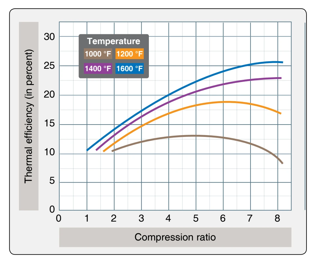
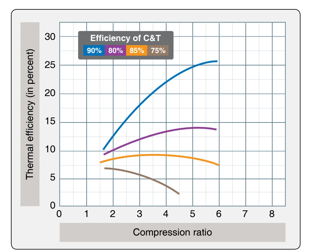
Thermal efficiency is a prime factor in gas turbine performance. It is the ratio of net work produced by the engine to the chemical energy supplied in the form of fuel. The three most important factors affecting the thermal efficiency are turbine inlet temperature, compression ratio, and the component efficiencies of the compressor and turbine. Other factors that affect thermal efficiency are compressor inlet temperature and combustion efficiency. Figure 1-81 shows the effect that changing compression ratio (compressor pressure ratio) has on thermal efficiency when compressor inlet temperature and the component efficiencies of the compressor and turbine remain constant. The effects that compressor and turbine component efficiencies have on thermal efficiency when turbine and compressor inlet temperatures remain constant are shown in Figure 1-82. In actual operation, the turbine engine exhaust temperature varies directly with turbine inlet temperature at a constant compression ratio.
Rpm is a direct measure of compression ratio; therefore, at constant rpm, maximum thermal efficiency can be obtained by maintaining the highest possible exhaust temperature. Since engine life is greatly reduced at high turbine inlet temperatures, the operator should not exceed the exhaust temperatures specified for continuous operation. Figure 1-83 illustrates the effect of turbine inlet temperature on turbine blade life. In the previous discussion, it was assumed that the state of the air at the inlet to the compressor remains constant. Since this is a practical application of a turbine engine, it becomes necessary to analyze the effect of varying inlet conditions on the thrust or power produced. The three principal variables that affect inlet conditions are the speed of the aircraft, the altitude of the aircraft, and the ambient temperature. To make the analysis simpler, the combination of these three variables can be represented by a single variable called stagnation density.
The power produced by a turbine engine is proportional to the stagnation density at the inlet. The next three illustrations show how changing the density by varying altitude, airspeed, and outside air temperature affects the power level of the engine. Figure 1-84 shows that the thrust output improves rapidly with a reduction in outside air temperature (OAT) at constant altitude, rpm, and airspeed. This increase occurs partly because the energy required per pound of airflow to drive the compressor varies directly with the temperature, leaving more energy to develop thrust. In addition, the thrust output increases since the air at reduced temperature has an increased density. The increase in density causes the mass flow through the engine to increase. The altitude effect on thrust, as shown in Figure 1-85, can also be discussed as a density and temperature effect. In this case, an increase in altitude causes a decrease in pressure and temperature.
Since the temperature lapse rate is lower than the pressure lapse rate as altitude is increased, the density is decreased. Although the decreased temperature increases thrust, the effect of decreased density more than offsets the effect of the colder temperature. The net result of increased altitude is a reduction in the thrust output.
The effect of airspeed on the thrust of a gas-turbine engine is shown in Figure 1-86. To explain the airspeed effect, it is necessary to understand first the effect of airspeed on the factors that combine to produce net thrust: specific thrust and engine airflow. Specific thrust is the net thrust in pounds developed per pound of airflow per second. It is the remainder of specific gross thrust minus specific ram drag. As airspeed is increased, ram drag increases rapidly. The exhaust velocity remains relatively constant; thus, the effect of the increase in