
Chapter 1
Aircraft Engines
Knuckle Pins
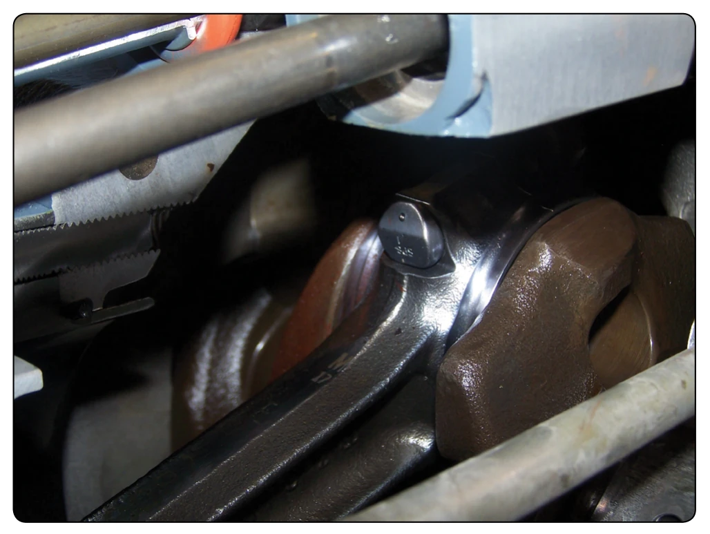
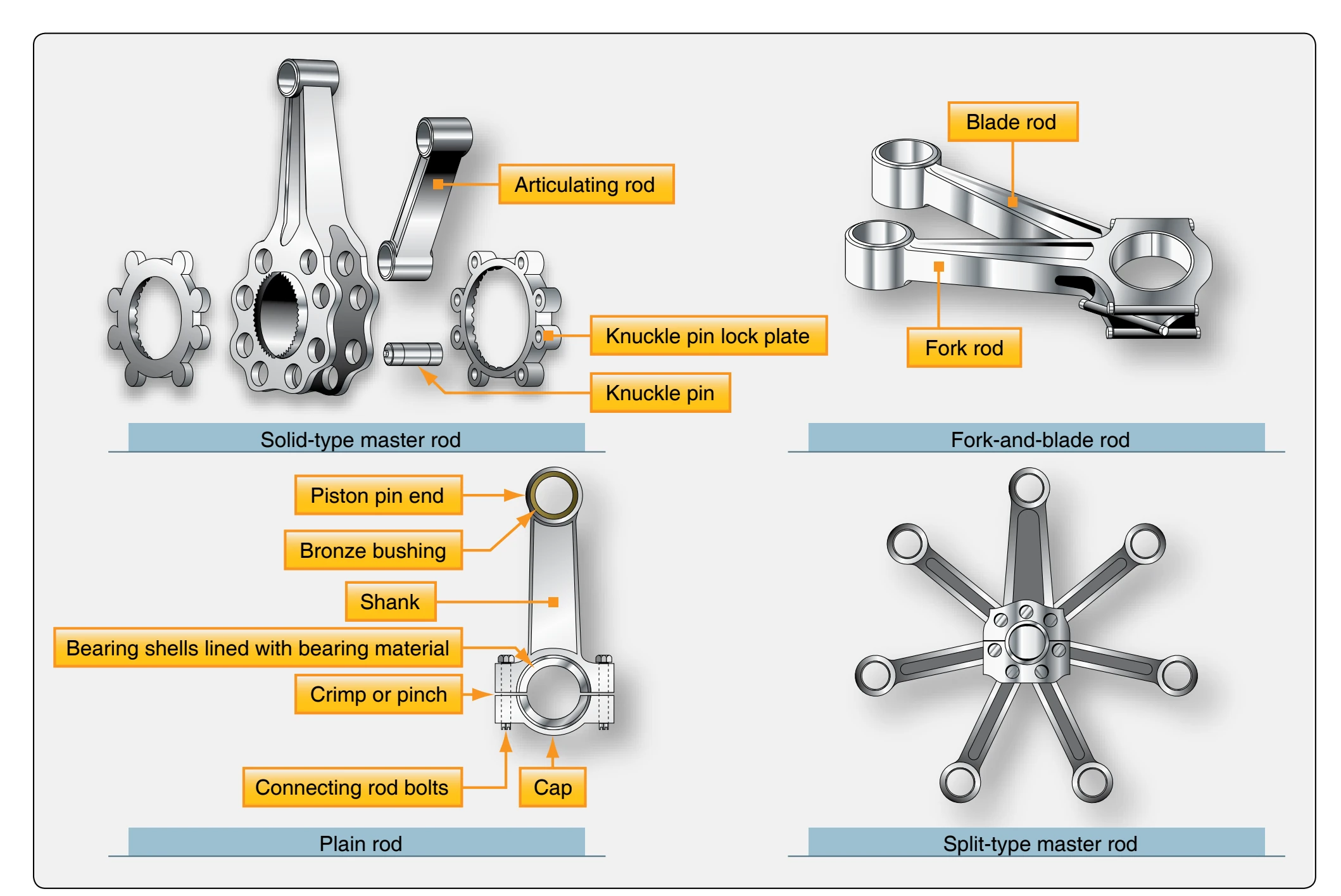
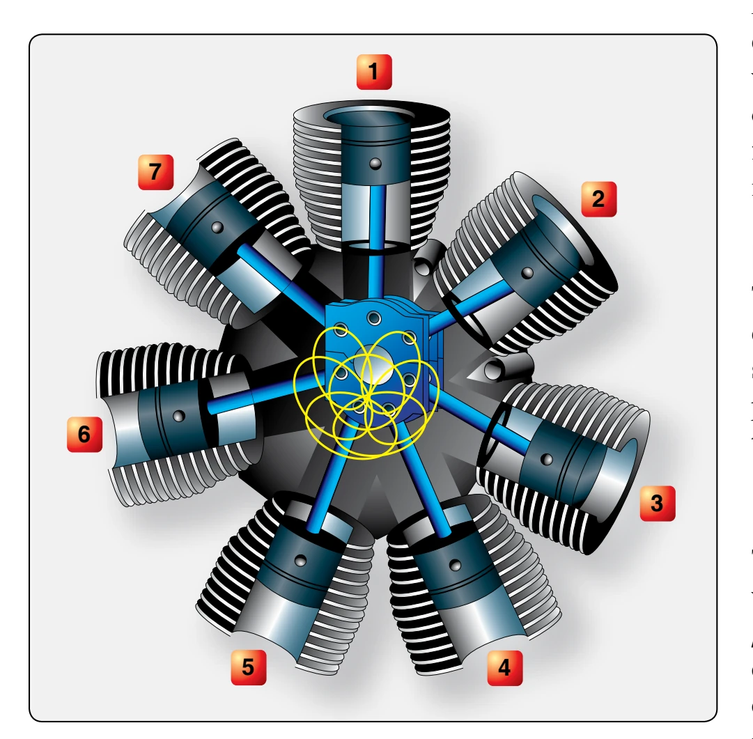
The knuckle pins are of solid construction except for the oil passages drilled in the pins, which lubricate the knuckle pin bushings. These pins may be installed by pressing into holes in the master rod flanges so that they are prevented from turning in the master rod. Knuckle pins may also be installed with a loose fit so that they can turn in the master rod flange holes, and also turn in the articulating rod bushings. These are called full-floating knuckle pins. In either type of installation, a lock plate on each side retains the knuckle pin and prevents a lateral movement.
Plain-Type Connecting Rods
Plain-type connecting rods are used in inline and opposed engines. The end of the rod attached to the crankpin is fitted with a cap and a two-piece bearing. The bearing cap is held on the end of the rod by bolts or studs. To maintain proper fit and balance, connecting rods should always be replaced in the same cylinder and in the same relative position.
Fork-and-Blade Rod Assembly
The fork-and-blade rod assembly is used primarily in V-type engines. The forked rod is split at the crankpin end to allow space for the blade rod to fit between the prongs. A single twopiece bearing is used on the crankshaft end of the rod. This type of connecting rod is not used much on modern engines.
Pistons
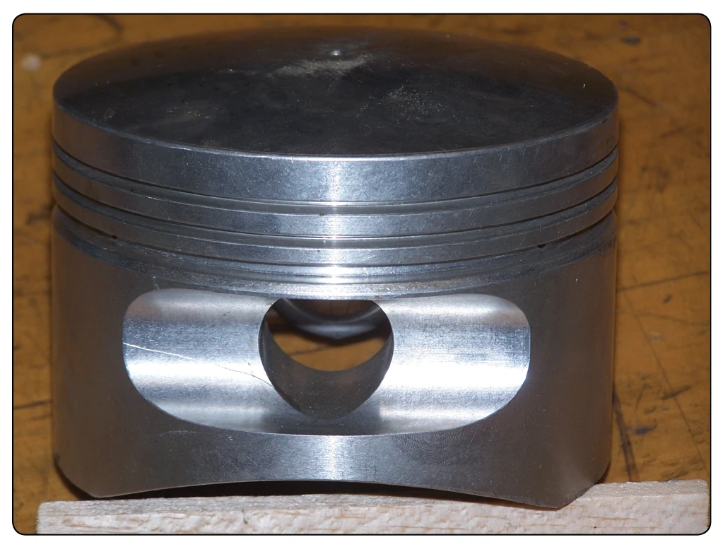
The piston of a reciprocating engine is a cylindrical member which moves back and forth within a steel cylinder. [Figure 1-13] The piston acts as a moving wall within the combustion chamber. As the piston moves down in the cylinder, it draws in the air-fuel mixture. As it moves upward, it compresses the charge, ignition occurs, and the expanding gases force the piston downward. This force is transmitted to the crankshaft through the connecting rod. On the return upward stroke, the piston forces the exhaust gases from the cylinder and the cycle repeats.
Piston Construction
The majority of aircraft engine pistons are machined from aluminum alloy forgings. Grooves are machined in the outside surface of the piston to receive the piston rings, and cooling fins are provided on the inside of the piston for greater heat transfer to the engine oil.
Pistons may be either the trunk type or the slipper type. [Figure 1-14] Slipper-type pistons are not used in modern, strength or wear resistance. The top of the piston, or head, may be flat, convex, or concave. Recesses may be machined in the piston head to prevent interference with the valves.
Modern engines use cam ground pistons that are a larger diameter perpendicular to the piston pin. This larger diameter keeps the piston straight in the cylinder as the engine warms up from initial startup. As the piston heats up during warm up, the part of the piston in line with the pin has more mass and expands more making the piston completely round. At low temperatures, the piston is oval shaped and, when it warms to operating temperature, it becomes round. This process reduces the tendency of the piston to cock or slap in the cylinder during warm up. When the engine reaches its normal operating temperature, the piston assumes the correct dimensions in the cylinder.
As many as six grooves may be machined around the piston to accommodate the compression rings and oil rings. [Figure 1-15] The compression rings are installed in the three uppermost grooves; the oil control rings are installed immediately above the piston pin. The piston is usually drilled at the oil control ring grooves to allow surplus oil scraped from the cylinder walls by the oil control rings to pass back into the crankcase. An oil scraper ring is installed at the base of the piston wall or skirt to prevent excessive oil
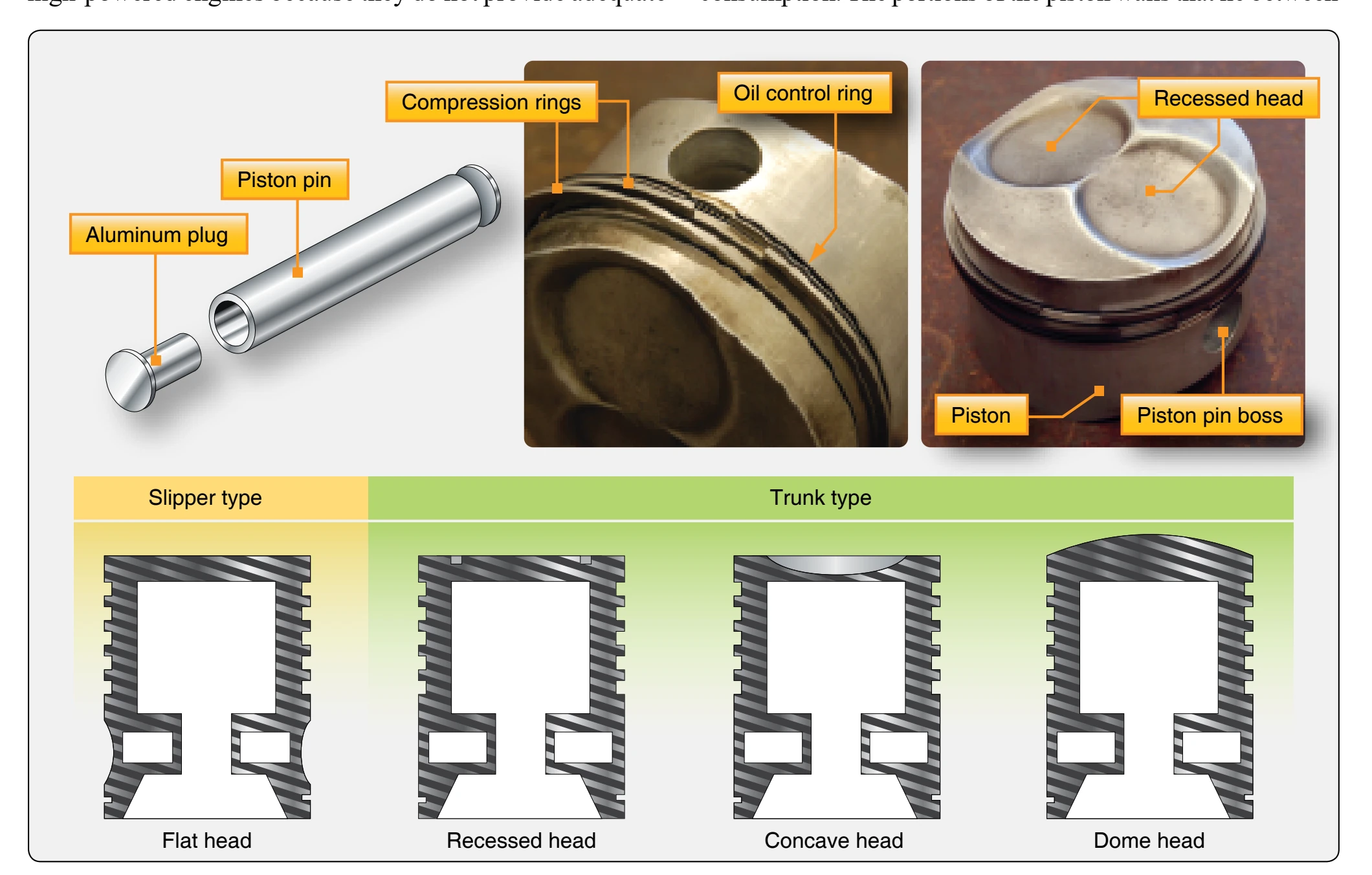
ring grooves are called the ring lands. In addition to acting as a guide for the piston head, the piston skirt incorporates the piston-pin bosses. The piston-pin bosses are of heavy construction to enable the heavy load on the piston head to be transferred to the piston pin.