
Chapter 10
Engine Maintenance & Operation
Because of the thin-sheet construction of hollow vanes, blending on the concave and convex surfaces, including the leading edge, is limited. Small, shallow dents are acceptable if the damage is of a rounded or gradual contour type and not a sharp or V-type, and if no cracking or tearing of vane material is evident in the damaged area.
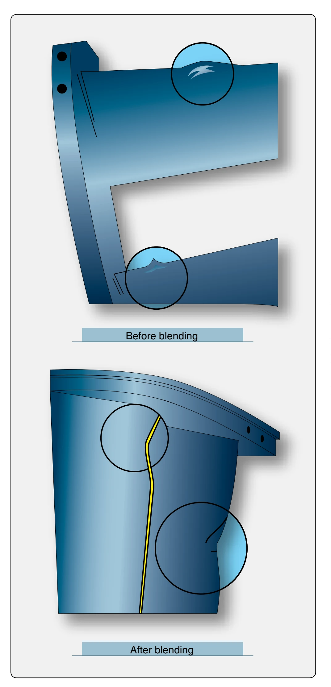
Trailing edge damage may be blended, if one-third of the weld seam remains after repair. [Figure 10-62] Concave surfaces of rubber-filled vanes may have allowable cracks extending inward from the outer airfoil, provided there is no suggestion of pieces breaking away. Using a light and mirror, inspect each guide vane trailing edge and vane body for cracks or damage caused by foreign objects.
Any inspection and repair of turbine compressor section components require that the technician always use the specific manufacturer’s current information for evaluation and limits of repairs.
Combustion Section Inspection
One of the controlling factors in the service life of the turbine engine is the inspection and cleaning of the hot section. Emphasis must be placed on the importance of careful inspection and repair of this section.
The following are general procedures for performing a hot section (turbine and combustion section) inspection. It is not intended to imply that these procedures are to be followed when performing repairs or inspections on turbine engines. However, the various practices are typical of those used on many turbine engines. Where a clearance or tolerance is shown, it is for illustrative purposes only. Always follow the instructions contained in the applicable manufacturer's maintenance and overhaul manuals.
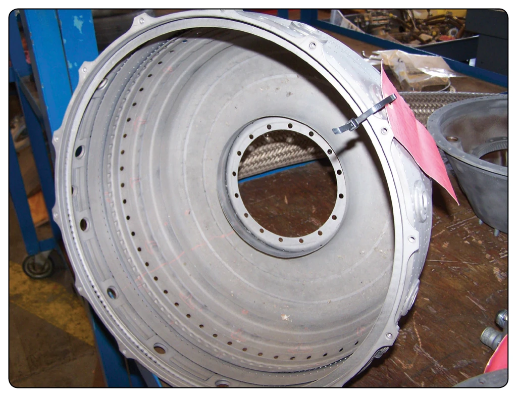
The entire external combustion case should be inspected for evidence of hot spots, exhaust leaks, and distortions before the case is opened. After the combustion case has been opened, the combustion chambers can be inspected for localized overheating, cracks, or excessive wear. [Figure 10-63] Inspect the first stage turbine blades and nozzle guide vanes for cracks, warping, or FOD. Also inspect the combustion chamber outlet ducts and turbine nozzle for cracks and for evidence of FOD.
One of the most frequent discrepancies that are detected while inspecting the hot section of a turbine engine is cracking. These cracks may occur in many forms, and the only way to determine that they are within acceptable limits or if they are allowed at all, is to refer to the applicable engine manufacturer’s service and overhaul manuals.
Cleaning the hot section is not usually necessary for a repair in the field, but in areas of high salt water or other chemicals a turbine rinse should be accomplished.
Engine parts can be degreased by using the emulsion-type cleaners or chlorinated solvents. The emulsion-type cleaners are safe for all metals, since they are neutral and noncorrosive. Cleaning parts by the chlorinated solvent method leaves the parts absolutely dry. If they are not to be subjected to further cleaning operations, they should be sprayed with a corrosionpreventive solution to protect them against rust or corrosion.
The hot section, which generally includes the combustion section and turbine sections, normally require inspections at regular intervals. The extent of disassembly of the engine to accomplish this inspection varies from different engine types. Most engines require that the combustion case be open for the inspection of the hot section. However, in performing this disassembly, numerous associated parts are readily accessible for inspection. The importance of properly supporting the engine and the parts being removed cannot be overstressed.
The alignment of components being removed and installed is also of the utmost importance. After all the inspections and repairs are made, the manufacturer’s detailed assembly instructions should be followed. These instructions are important in efficient engine maintenance, and the ultimate life and performance of the engine. Extreme care must be
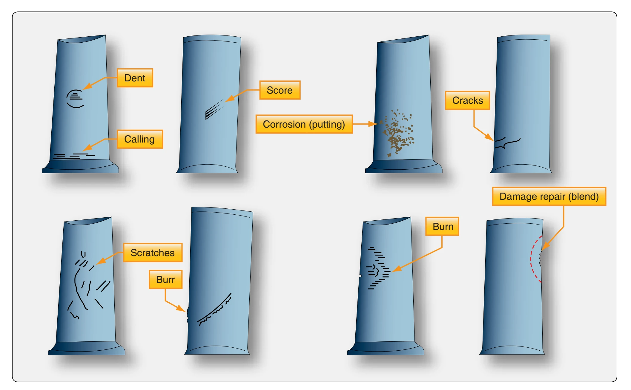
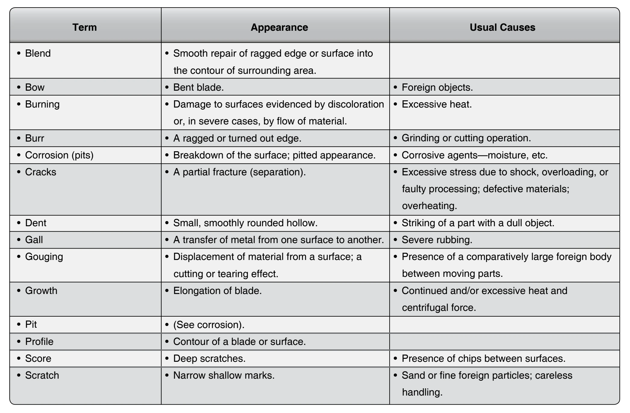
taken during assembly to prevent dirt, dust, cotter pins, lock wire, nuts, washers, or other foreign material from entering the engine.
Marking Materials for Combustion Section Parts
Certain materials may be used for temporary marking during assembly and disassembly. Always refer to manufacturer’s information for marking parts. Layout dye (lightly applied), a felt tip marker, or chalk may be used to mark parts that are
directly exposed to the engine’s gas path, such as turbine blades and discs, turbine vanes, and combustion chamber liners. A wax marking pencil may be used for parts that are not directly exposed to the gas path. Do not use a wax marking pencil on a liner surface or a turbine rotor. The use of carbon alloy or metallic pencils is not recommended because of the possibility of causing intergranular corrosion attack, that could result in a reduction in material strength and cracking.