
Chapter 10
Engine Maintenance & Operation
Inspection & Repair of Combustion Chambers
Inspect the combustion chambers and covers for cracks by using visible dye or fluorescent penetrant inspection method. Any cracks, nicks, or dents are usually cause for rejecting the component. Inspect the covers, noting particularly the area around the fuel drain bosses for any pits or corrosion. When repairing the combustion chamber liner, the procedures given in the appropriate engine manufacturer’s overhaul instruction manual should be followed. If there is doubt that the liner is serviceable, it should be replaced.
Combustion chambers should be replaced or repaired if two cracks are progressing from a free edge so that their meeting is imminent and could allow a piece of metal that could cause turbine damage to break loose. Separate cracks in the baffle are acceptable. Cracks in the cone are rare but, at any location on this component, is cause for rejection of the liner. Cracks in the swirl vanes are cause for rejection of the liner. Loose swirl vanes may be repaired by silver brazing. Cracks in the front liner emanating from the air holes are acceptable, provided they do not exceed allowable limits. If such cracks fork or link with others, the liner must be repaired. If two cracks originating from the same air hole are diametrically opposite, the liner is acceptable. Radial cracks extending from the interconnector and spark igniter boss are acceptable, if they do not exceed allowable limits and if such cracks do not fork or link with others. Circumferential cracks around the boss pads should be repaired prior to re-use of the liner. Baffle cracks connecting more than two holes should be repaired.
After long periods of engine operation, the external surfaces of the combustion chamber liner location pads often show signs of fretting. This is acceptable, provided no resultant cracks or perforation of the metal is apparent. Any cover or chamber inadvertently dropped on a hard surface or mishandled should be thoroughly inspected for minute cracks that may elongate over a period of time and then open, creating a hazard.
Parts may be found where localized areas have been heated to an extent to buckle small portions of the chamber. Such parts are considered acceptable if the burning of the part has not progressed into an adjacent welded area, or to such an extent as to weaken the structure of the liner weldment. Buckling of the combustion chamber liner can be corrected by straightening the liner. Moderate buckling and associated cracks are acceptable in the row of cooling holes. More severe buckling that produces a pronounced shortening or tilting of the liner is cause for rejection. Upon completion of the repairs by welding, the liner should be restored as closely as possible to its original shape.
Fuel Nozzle & Support Assemblies
Clean all carbon deposits from the nozzles by washing with a cleaning fluid approved by the engine manufacturer and remove the softened deposits with a soft bristle brush. It is desirable to have filtered air passing through the nozzle during the cleaning operation to carry away deposits as they are loosened. Make sure all parts are clean. Dry the assemblies with clean, filtered air. Because the spray characteristics of the nozzle may become impaired, no attempt should be made to clean the nozzles by scraping with a hard implement or by rubbing with a wire brush. Inspect each component part of the fuel nozzle assembly for nicks and burrs. Many fuel nozzles can be checked by flowing fluid through the nozzle under pressure and closely checking the flow pattern coming for the nozzle.
Turbine Disc Inspection
The inspection for cracks is very important because cracks are not normally allowed. Crack detection, when dealing with the turbine disc and blades, is mostly visual, although structural inspection techniques can be used, such as penetrant methods and others to aid in the inspection. Cracks on the disc necessitate the rejection of the disc and replacement of the turbine rotor. Slight pitting caused by the impingement of foreign matter may be blended by stoning and polishing.
Turbine Blade Inspection
Turbine blades are usually inspected and cleaned in the same manner as compressor blades. However, because of the extreme heat under which the turbine blades operate, they are more susceptible to damage. Using a strong light and a magnifying glass, inspect the turbine blades for stress rupture cracks and deformation of the leading edge. [Figures 10-64 and 10-65]
Stress rupture cracks usually appear as minute hairline cracks on or across the leading or trailing edge at a right angle to the edge length. Visible cracks may range in length from one-sixteenth inch upward. Deformation, caused by over-temperature, may appear as waviness and/or areas of varying airfoil thickness along the leading edge. The leading edge must be straight and of uniform thickness along its entire length, except for areas repaired by blending. Do not confuse stress rupture cracks or deformation of the leading edge with foreign material impingement damage or with
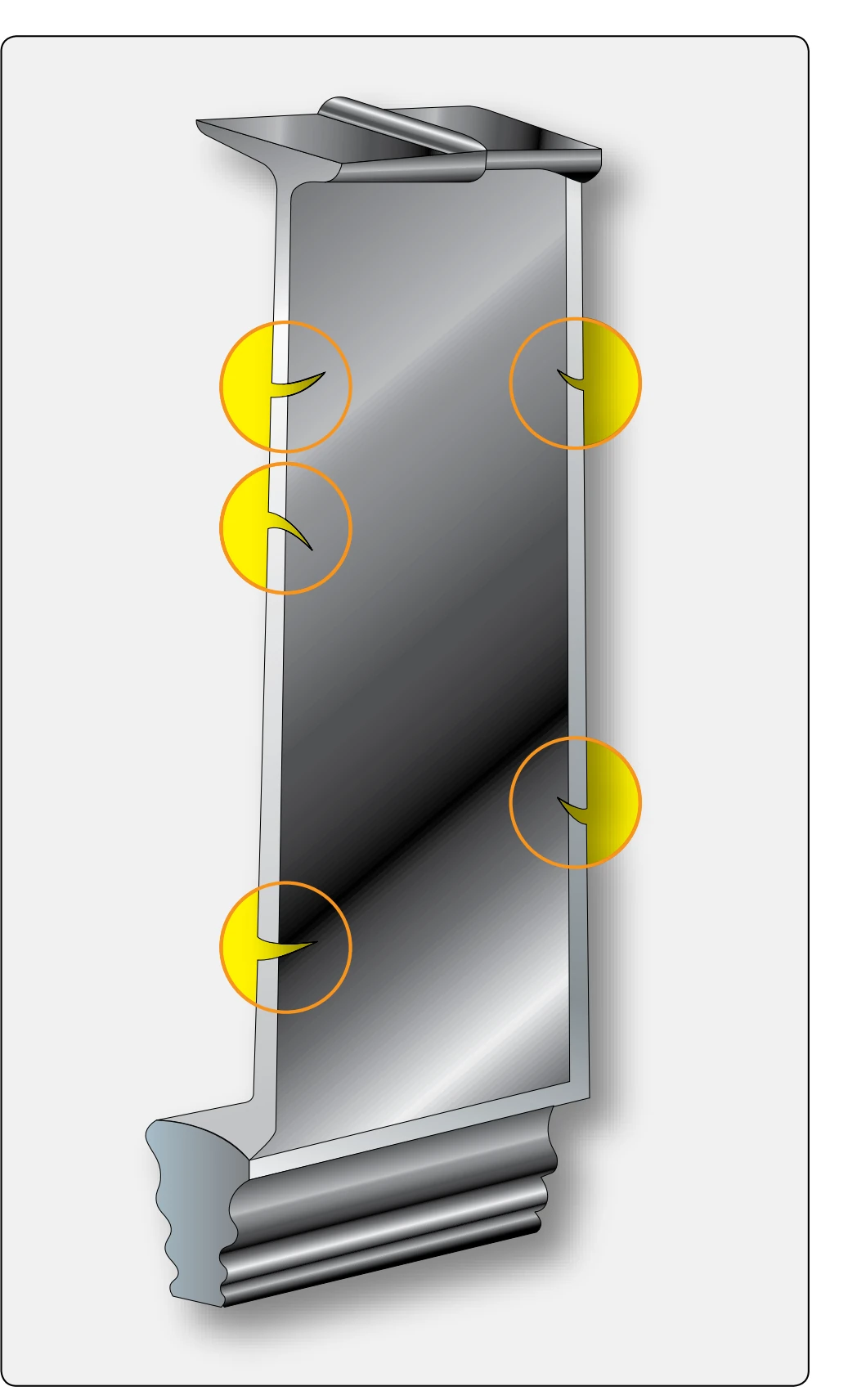
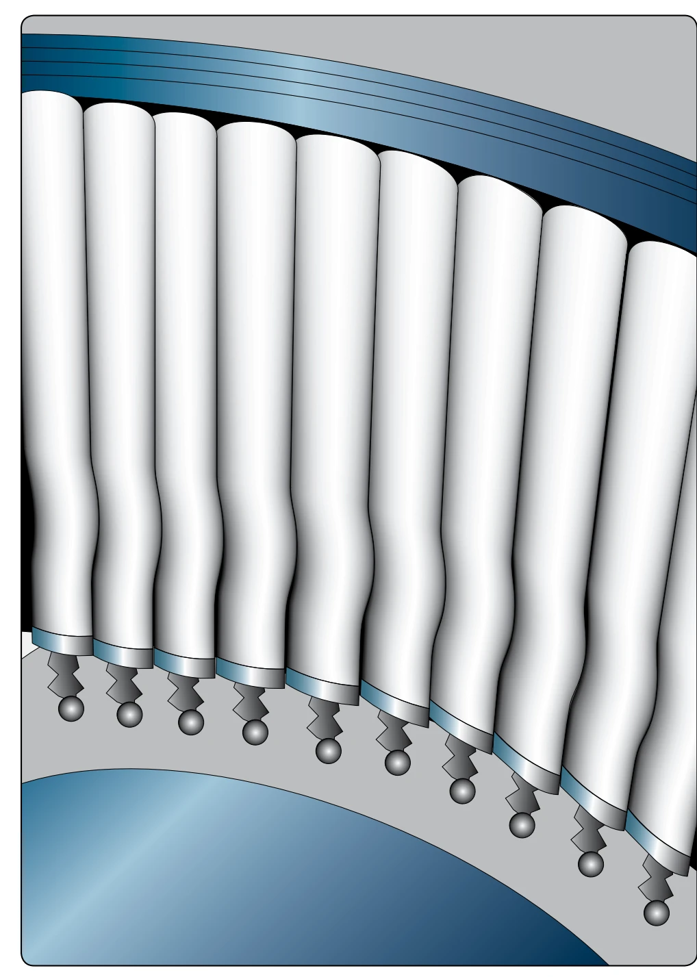
blending repairs to the blade. When any stress rupture cracks or deformation of the leading edges of the first-stage turbine blades are found, an over-temperature condition must be suspected. Check the individual blades for stretch and the turbine disc for hardness and stretch. Blades removed for a detailed inspection or for a check of turbine disc stretch must be re-installed in the same slots from which they were removed. Number the blades prior to removal.
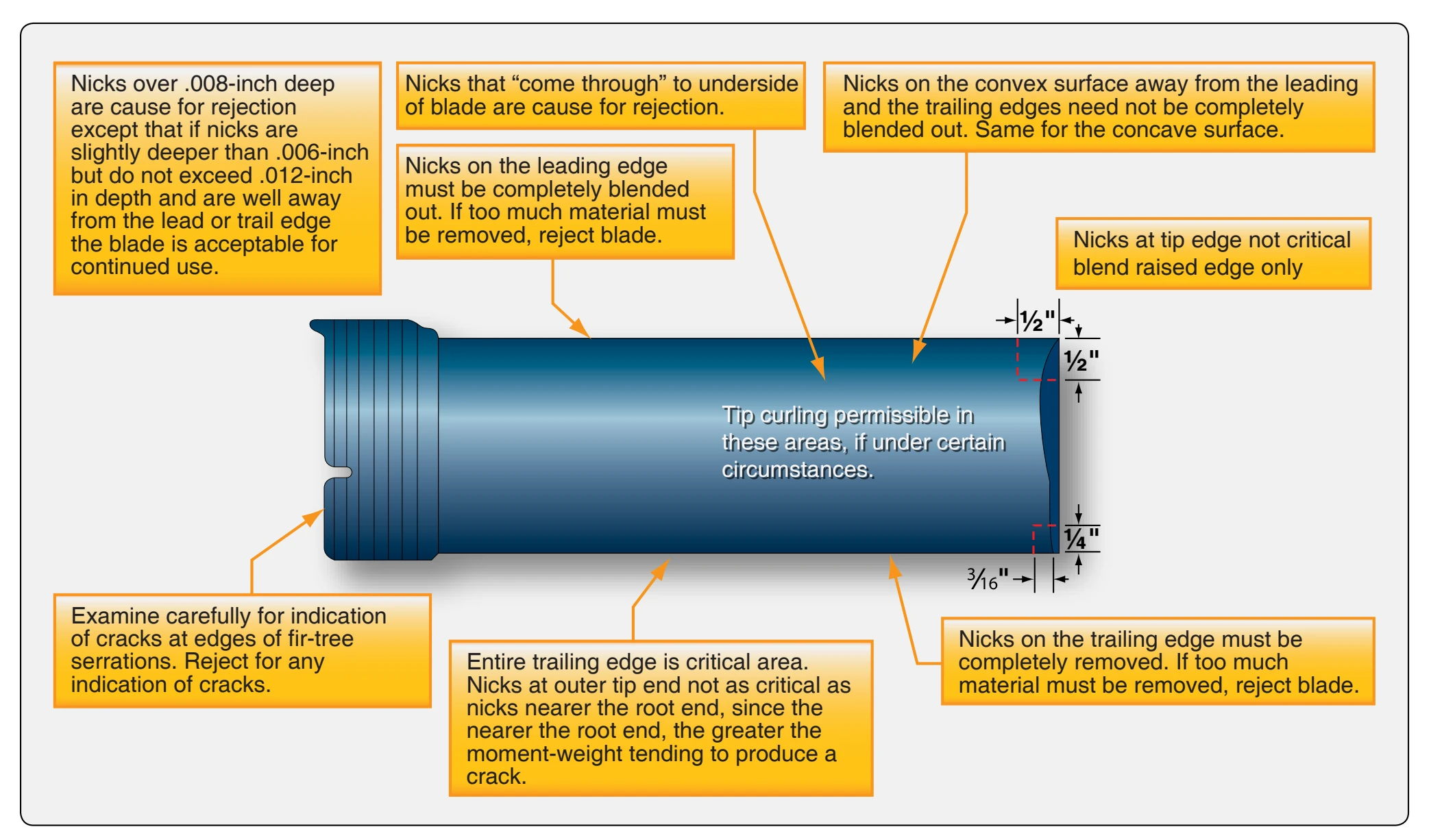
The turbine blade outer shroud should be inspected for air seal wear. If shroud wear is found, measure the thickness of the shroud at the worn area. Use a micrometer or another suitable and accurate measuring device that ensures a good reading in the bottom of the comparatively narrow wear groove. If the remaining radial thickness of the shroud is less than that specified, the stretched blade must be replaced. Typical blade inspection requirements are indicated in Figure 10-66. Blade tip curling within a one-half inch square area on the leading edge of the blade tip is usually acceptable if the curling is not sharp. Curling is acceptable on the trailing edge if it does not extend beyond the allowable area. Any sharp bends that may result in cracking or a piece breaking out of the turbine blade is cause for rejection, even though the curl may be within the allowable limits. Each turbine blade should be inspected for cracks.
Turbine Blade Replacement Procedure
Turbine blades are generally replaceable, subject to momentweight limitations. These limitations are contained in the
engine manufacturer’s applicable technical instructions. If visual inspection of the turbine assembly discloses several broken, cracked, or eroded blades, replacing the entire turbine assembly may be more economical than replacing the damaged blades. [Figure 10-67]