Chapter 10
Engine Maintenance & Operation
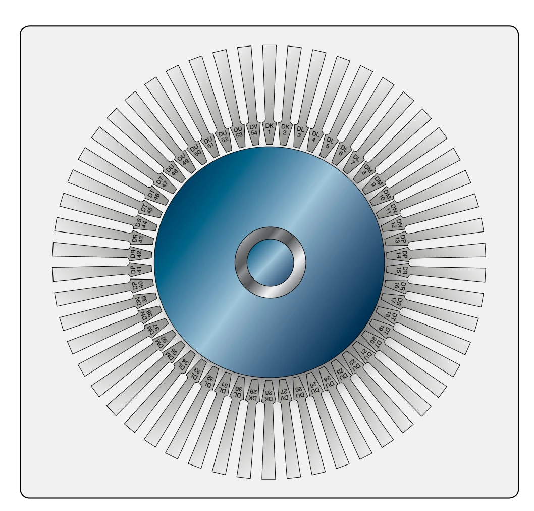
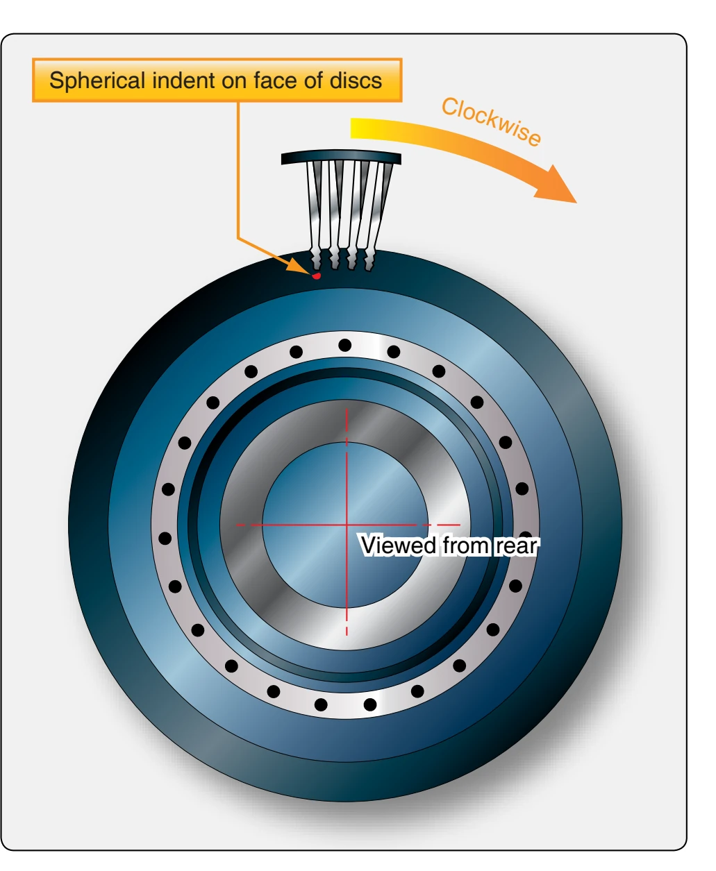
In the initial buildup of the turbine, a complete set of 54 blades made in coded pairs (two blades having the same code letters) is laid out on a bench in the order of diminishing moment-weight. The code letters, indicating the momentweight balance in ounces, are marked on the rear face of the fir-tree section of the blade (viewing the blade as installed at final assembly of the engine). The pair of blades having the heaviest moment-weight is numbered 1 and 28; the next heaviest pair of blades is numbered 2 and 29; the third heaviest pair is numbered 3 and 30. This is continued until all the blades have been numbered. Mark a number 1 on the face of the hub on the turbine disc. The number 1 blade is then installed adjacent to the number 1 on the disc. [Figure 10-68]
The remaining blades are then installed consecutively in a clockwise direction, viewed from the rear face of the turbine disc. If there are several pairs of blades having the same code letters, they are installed consecutively before going to the next code letters. If a blade requires replacement, the diametrically opposite blade must also be replaced. Computer programs generally determine the location for turbine blades for turbine wheels on modern engines.
Turbine Nozzle Inlet Guide Vane Inspection
After removing the required components, the first stage turbine blades and turbine nozzle vanes are accessible
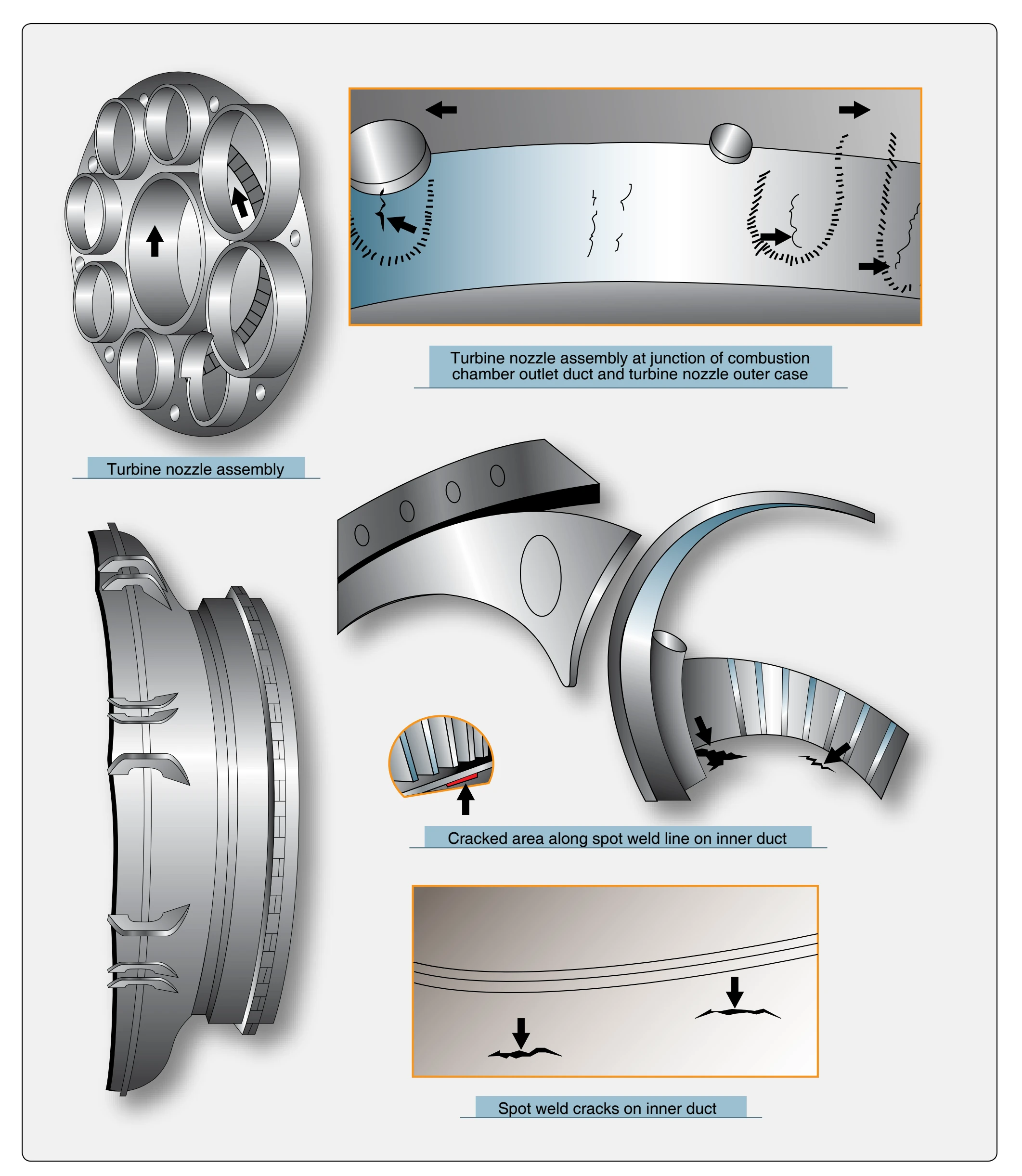
for inspection. The blade limits specified in the engine manufacturer’s overhaul and service instruction manual should he adhered to. Figure 10-69 shows where cracks usually occur on a turbine nozzle assembly. Slight nicks and dents are permissible if the depth of damage is within limits. Inspect the nozzle vanes for nicks or cracks. Small nicks are not cause for vane rejection, provided such nicks blend out smoothly.
Inspect the nozzle vane supports for defects caused by the impingement of foreign particles. Use a stone to blend any doubtful nicks to a smooth radius. Like turbine blades, it is possible to replace a maximum number of turbine nozzle vanes in some engines. If more than the maximum vanes are damaged, a new turbine nozzle vane assembly must be installed. With the tailpipe (exhaust nozzle) removed, the rear turbine stage can be inspected for any cracks or evidence of blade stretch. Additional nozzle stages can also be inspected with a strong light by looking through the rear-stage turbine.
Clearances
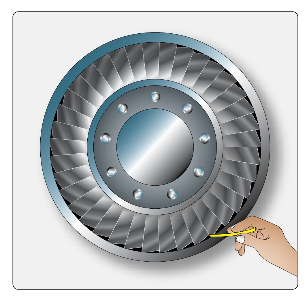
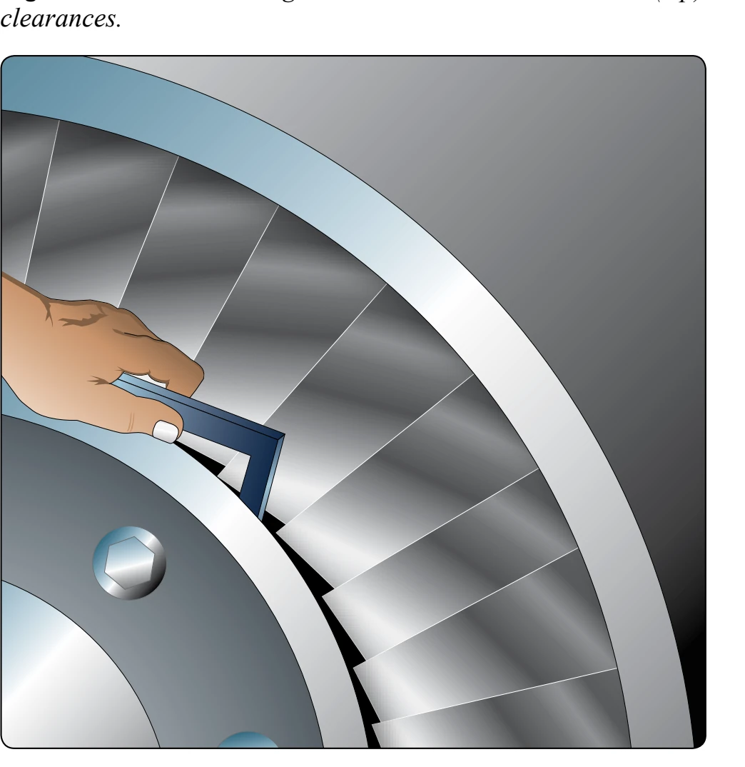
Checking the clearances is one of the procedures in the maintenance of the turbine section of a turbine engine. The manufacturer’s service and overhaul manual gives the procedures and tolerances for checking the turbine. Turbine clearances being measured at various locations are shown in Figures 10-70 and 10-71. To obtain accurate readings, special tools provided by each manufacturer must be used
as described in the service instructions for specific engines.
Exhaust Section
The exhaust section of the turbine engine is susceptible to heat cracking. This section must be thoroughly inspected along with the inspection the combustion section and turbine section of the engine. Inspect the exhaust cone and exhaust nozzle for cracks, warping, buckling, or hot spots. Hot spots on the tail cone are a good indication of a malfunctioning fuel nozzle or combustion chamber.
The inspection and repair procedures for the hot section of any one gas turbine engine share similarities to those of other gas turbine engines. One usual difference is the nomenclature applied to the various parts of the hot section by the different manufacturers. Other differences include the manner of disassembly, the tooling necessary, and the repair methods and limits.
Engine Ratings
The flat rating of a turbine engine is the thrust performance that is guaranteed by the manufacturer for a new engine under specific operating conditions, such as takeoff, maximum continuous climb, and cruise power settings. The turbine inlet temperature is proportional to the energy available to turn the turbine. This means that the hotter the gases are that are entering the turbine section of the engine, the more power is available to turn the turbine wheel. The exhaust temperature is proportional to the turbine inlet temperature. Regardless of how or where the exhaust temperature is taken on the engine for the flight deck reading, this temperature is proportional to the temperature of the exhaust gases entering the first stage of inlet guide vanes. A higher EGT corresponds to a larger amount of energy to the turbine so it can turn the compressor faster. This works fine until the temperature reaches a point when the turbine inlet guide vanes start to be damaged. EGT must be held constant or lowered as the result of a prolonged hot section life and, at the same time, provide the thrust to meet the certification requirements.
Before high bypass turbofan engines, some older types of engines used water injection to increase thrust for takeoff (wet). This is the maximum allowable thrust for takeoff. The rating is obtained by actuating the water-injection system and setting the computed wet thrust with the throttle, in terms of a predetermined turbine discharge pressure or engine pressure ratio for the prevailing ambient conditions. The rating is restricted to takeoff, is time-limited, and has an altitude limitation. Water injection is not used very much on turbine engines any more.