
Chapter 10
Engine Maintenance & Operation
To ensure that fuel remains in the lines and that the enginedriven fuel pumps are not starved for fuel that lubricates the pumps, the aircraft fuel boost pump must be turned off after, not before, the throttle or the fuel shutoff lever is placed in the OFF position.
Generally, an engine should not be shut down by the fuel shutoff lever until after the aircraft throttle has been retarded to idle. Because the fuel shutoff valve is located on the fuel control discharge, a shutdown from high thrust settings results in high fuel pressures within the control that can harm the fuel system parts.
When an accurate reading of the oil level in the oil tank is needed following an engine shutdown, the engine should be operated and shut down with the oil check taking place within not more than 30 minutes after shutdown. Check the engine manuals for the specific procedure.
Troubleshooting Turbine Engines
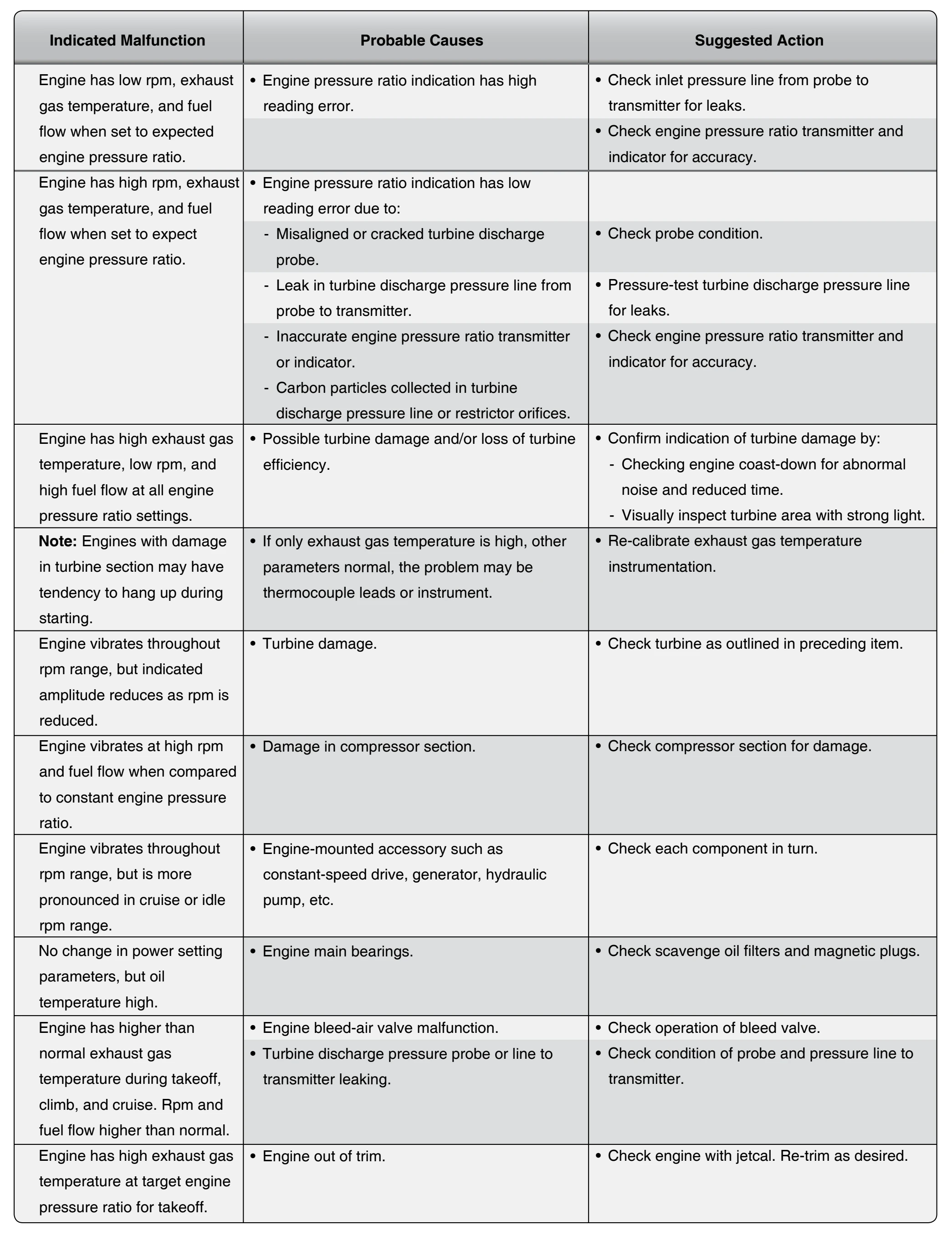
Included in this section are typical guidelines for locating engine malfunctions on most turbine engines. Since it would be impractical to list all the malfunctions that could occur, only the most common malfunctions are covered. A thorough knowledge of the engine systems, applied with logical reasoning, solves most problems that may occur.
Figure 10-75 enumerates some malfunctions that may be encountered. Possible causes and suggested actions are given in the adjacent columns. The malfunctions presented herein are solely for the purpose of illustration and should not be construed to have general application. For exact information about a specific engine model, consult the applicable manufacturer’s instructions.
Turboprop Operation
Turboprop engine operation is quite similar to that of a turbojet engine, except for the added feature of a propeller.
The starting procedure and the various operational features are very much alike. The turboprop chiefly requires attention to engine operating limits, the throttle or power lever setting, and the torquemeter pressure gauge. Although torquemeters indicate only the power being supplied to the propeller and not the equivalent shaft horsepower, torquemeter pressure is approximately proportional to the total power output and, thus, is used as a measure of engine performance. The torquemeter pressure gauge reading during the takeoff engine check is an important value. It is usually necessary to compute the takeoff power in the same manner as is done for a turbojet engine. This computation is to determine the maximum allowable exhaust gas temperature and the torquemeter pressure that a normally functioning engine should produce for the outside, or ambient, air temperature and barometric pressure prevailing at the time.
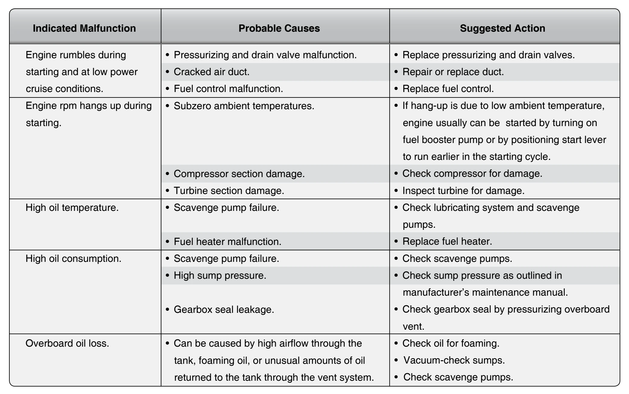
Troubleshooting Procedures for Turboprop Engines
All test run-ups, inspections, and troubleshooting should be performed in accordance with the applicable engine manufacturer’s instructions. In Figure 10-76, the troubleshooting procedure for the turboprop reduction gear, torquemeter, and power section are combined because of their inter-relationships. The table includes the principal troubles, together with their probable causes and remedies.
Turbine Engine Calibration & Testing
Some of the most important factors affecting turbine engine life are EGT, engine cycles (a cycle is generally a takeoff and landing) and engine speed. Excess EGT of a few degrees reduces turbine component life. Low EGT materially reduces turbine engine efficiency and thrust. So, to make the engine highly efficient, the exhaust temperatures need to be as high as possible, while maintaining an EGT operating temperature that does not damage the turbine section of the engine. If the engine is operated at excess exhaust temperatures, engine deterioration occurs. Since the EGT temperature is set by the EGT temperature gauge, it is imperative that it is accurate. Excessive engine speed can cause premature engine wear and, if extreme, can cause engine failure.
One older type of calibration test unit used to analyze the turbine engine is the jetcal analyzer. [Figure 10-77] A jetcal analyzer is a portable instrument made of aluminum, stainless steel, and plastic. The major components of the analyzer are the thermocouple, rpm, EGT indicator, resistance, and insulation check circuits, as well as the potentiometer, temperature regulators, meters, switches, and all the necessary cables, probes, and adapters for performing all tests.
Turbine Engine Analyzer Uses
Many different types of analyzers are used each with its own function, including onboard systems that use computers to
test aircraft systems. Depending upon the specific analyzer used, procedures vary somewhat, but the basic test are outlined here. Always refer to the specific instructions associated with the analyzer being used.
Most analyzers may be used to: