
Chapter 10
Engine Maintenance & Operation
- Functionally check the aircraft EGT system for error, without running the engine or disconnecting the wiring.
- Check individual thermocouples before placement in a parallel harness.
- Check each engine thermocouple in a parallel harness for continuity.
- Check the thermocouples and parallel harness for accuracy.
- Check the resistance of the EGT circuit.
- Check the insulation of the EGT circuit for shorts to ground, or for shorts between leads.
- Check EGT indicators, either in or out of the aircraft, for error.
- Determine engine rpm accuracy during engine testing. Added to this is the checking and troubleshooting of the aircraft tachometer system.
- Establish the proper relationship between the EGT and engine rpm during engine run-up.
Analyzer Safety Precautions
Observe the following safety precautions while operating the engine analyzer or other types of test equipment:
- Never use a voltammeter to check the potentiometer for continuity. If a voltammeter is used, damage to the galvanometer and standard battery cell results.
- Check the thermocouple harness before engine run-up. This must be done because the circuit must be correct before the thermocouples can be used for true EGT pickup.
- For safety, ground the jetcal analyzer when using an AC power supply. Any electrical equipment operated on AC power and utilizing wire-wound coils, such as the probes with the jetcal analyzer, has an induced voltage on the case that can be discharged if the equipment is not grounded. This condition is not apparent during dry weather, but on damp days the operator can be shocked slightly. Therefore, for the operator’s protection, the jetcal analyzer should be grounded using the pigtail lead in the power inlet cable.
- Use heater probes designed for use on the engine
thermocouples to be tested. Temperature gradients are very critical in the design of heater probes. Each type of aircraft thermocouple has its own specially designed probe. Never attempt to modify heater probes to test other types of thermocouples.
- Do not leave heater probe assemblies in the exhaust nozzle during engine run-up.
- Never allow the heater probes to go over 900 °C (1,652 °F). Exceeding these temperatures results in damage to the jetcal analyzer and heater probe assemblies.
Continuity Check of Aircraft EGT Circuit
To eliminate any error caused by one or more inoperative aircraft thermocouples, a continuity check is performed. The check is made by heating one heater probe to between 500 and 700 °C and placing the hot probe over each of the aircraft thermocouples, one at a time. The EGT indicator must show a temperature rise as each thermocouple is checked. When large numbers (eight or more) of thermocouples are used in the harness, it is difficult to see a rise on the aircraft instrument because of the electrical characteristics of a parallel circuit. Therefore, the temperature indication of the aircraft thermocouples is read on the potentiometer of the analyzer by using the check cable and necessary adapter.
Functional Check of Aircraft EGT Circuit
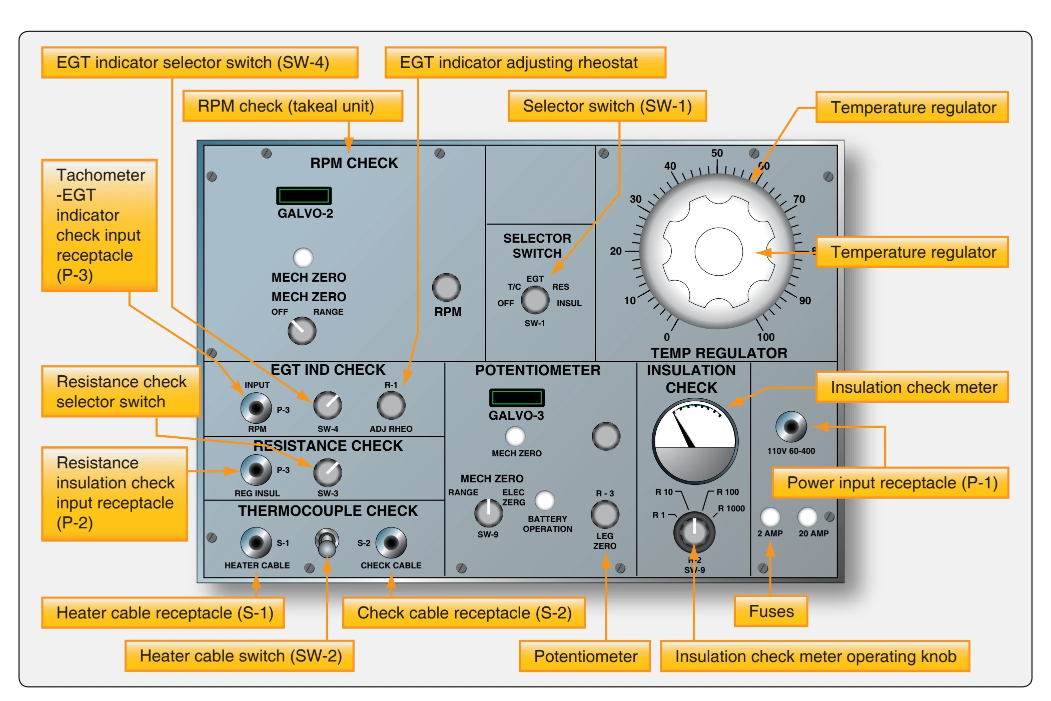
During the EGT system functional test and the thermocouple harness checks, the analyzer has a specific degree of accuracy at the test temperature, which is usually the maximum operating temperature of the turbine engine. [Figure 10-78] Each engine has its own maximum operating temperature, that can be found in applicable technical instructions.
The test is made by heating the engine thermocouples in the exhaust nozzle or turbine section to the engine test temperature. The heat is supplied by heater probes through the necessary cables. With the engine thermocouples hot, their temperature is registered on the aircraft EGT indicator. At the same time, the thermocouples embedded in the heater probes, which are completely isolated from the aircraft system, are picking up and registering the same temperature on the test analyzer.
The temperature registered on the aircraft EGT indicator should be within the specified tolerance of the aircraft system and the temperature reading on the temperature analyzer. When the temperature difference exceeds the allowable tolerance, troubleshoot the aircraft system.
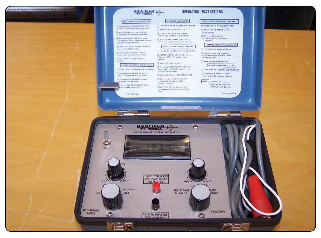
EGT Indicator Check
The EGT indicator is tested after being removed from the aircraft instrument panel and disconnected from the aircraft EGT circuit leads. Attach the instrument cable and EGT indicator adapter leads to the indicator terminals and place the indicator in its normal operating position. Adjust the analyzer switches to the proper settings. The indicator reading should correspond to the readings of the analyzer within the allowable limits of the EGT indicator.
Correction for ambient temperature is not required for this test, as both the EGT indicator and analyzer are temperature compensated. The temperature registered on the aircraft EGT indicator should be within the specified tolerance of the aircraft system and the temperature reading on the analyzer readout. When the temperature difference exceeds the allowable tolerance, troubleshoot the aircraft system.
Resistance & Insulation Check
The thermocouple harness continuity is checked while the EGT system is being checked functionally. The resistance of the thermocouple harness is held to very close tolerances, since a change in resistance changes the amount of current flow in the circuit. A change of resistance gives erroneous temperature readings. The resistance and insulation check circuits make it possible to analyze and isolate any error in the aircraft system. How the resistance and insulation circuits are used is discussed with troubleshooting procedures.