
Chapter 10
Engine Maintenance & Operation
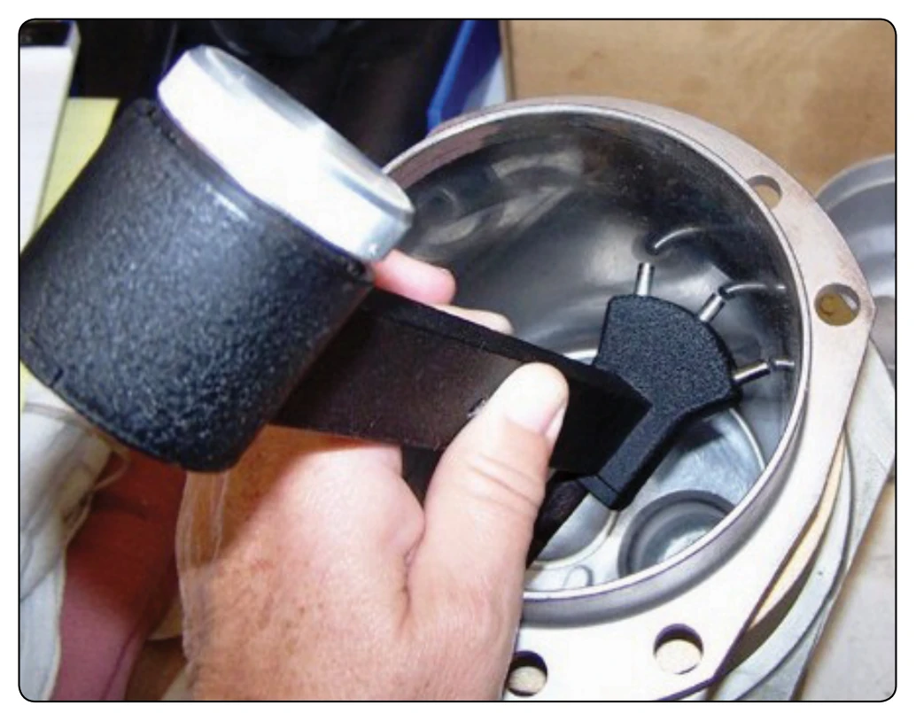
Inspect the cylinder barrel for wear, using a cylinder bore gauge [Figure 10-5], a telescopic gauge, and micrometer or an inside micrometer. Dimensional inspection of the barrel consists of the following measurements:
- Maximum taper of cylinder walls.
- Maximum out-of-roundness.
- Bore diameter.
- Step.
- Fit between piston skirt and cylinder.
All measurements involving cylinder barrel diameters must be taken at a minimum of two positions 90° apart in the particular plane being measured. It may be necessary to take more than two measurements to determine the maximum wear.
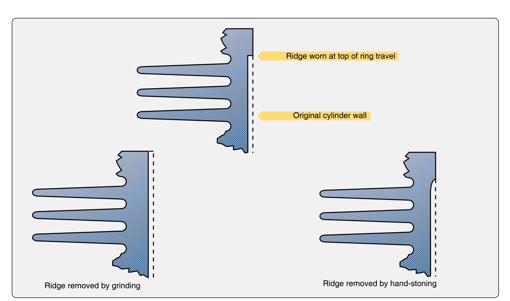
Taper of the cylinder walls is the difference between the diameter of the cylinder barrel at the bottom and the diameter at the top. The cylinder is usually worn larger at the top than at the bottom. This taper is caused by the natural wear pattern. At the top of the stroke, the piston is subjected to greater heat and pressure and more erosive environment than at the bottom of the stroke. Also, there is greater freedom of movement at the top of the stroke. Under these conditions, the piston wears the cylinder wall more at the top of the cylinder. In most cases, the taper ends with a ridge, that must be removed during overhaul. [Figure 10-6]
Where cylinders are built with an intentional choke, measurement of taper becomes more complicated. Cylinder choke is where the top of the cylinder has been made with the very top diameter of the cylinder smaller, to compensate for wear and expansion during operation. It is necessary to know exactly how the size indicates wear or taper. Taper can be measured in any cylinder by a cylinder dial gauge as long as there is not a sharp step. The dial gauge tends to ride up on the step and causes inaccurate readings at the top of the cylinder.
The measurement for out-of-roundness is usually taken at the top of the cylinder. However, a reading should also be taken at the skirt of the cylinder to detect dents or bends caused by careless handling. A step, or ridge, is formed in the cylinder by the wearing action of the piston rings. [Figure 10-6] The greatest wear is at the top of the ring travel limit. The ridge that results is likely to cause damage to the rings or piston. If the step exceeds tolerances, it should be removed by grinding the cylinder oversize, or it should be blended by hand-stoning to break the sharp edge.
A step also may be found where the bottom ring reaches the lowest travel. This step is rarely found to be excessive, but it should be checked.
Inspect the cylinder walls for rust, pitting, or scores. Mild damage of this sort can be removed when the cylinders are deglazed. With more extensive damage, the cylinder has to be reground or honed. If the damage is too deep to be removed by either of these methods, the cylinder usually will have to be rejected. Most engine manufacturers, or engine overhaul repair stations, have an exchange service on cylinders with damaged barrels.
Check the cylinder flange for warpage by placing the cylinder on a suitable jig. Check to see that the flange contacts the jig all the way around. The amount of warpage can be checked by using a thickness gauge. A cylinder whose flange is warped beyond the limits should be rejected.
Rocker Arms & Shafts
Inspect the valve rockers for cracks and worn, pitted, or scored tips. See that all oil passages are free from obstructions.
Inspect the shaft’s diameter for correct size with a micrometer. Rocker shafts are often found to be scored and burned because of excessive turning in the cylinder head. Also, there may be some pickup on the shaft (bronze from the rocker bushing transferred to the steel shaft). Generally, this is caused by overheating and too little clearance between shaft and bushing. The clearance between the shaft and the bushing is most important.
Inspect the rocker arm bushing for correct size. Check for proper clearance between the shaft and the bushing. Very often the bushings are scored because of mishandling during disassembly. Check to see that the oil holes line up..At least 50% of the hole in the bushing should align with the hole in the rocker arm.
On engines that use a bearing, rather than a bushing, inspect the bearing to make certain it has not been turning in the rocker arm boss. Also inspect the bearing to determine its serviceability.
Crankshaft
Use extreme care in inspecting and checking the crankshaft for straightness. Place the crankshaft in V-blocks, supported at the locations specified in the applicable engine overhaul manual as in Figure 10-7. Using a surface plate and a dial indicator, measure the shaft runout. If the total indicator reading exceeds the dimensions given in the manufacturer’s table of limits, the shaft must not be re-used. A bent crankshaft should not be straightened. Any attempt to do so results in rupture of the nitrided surface of the bearing journals, a condition that causes eventual failure of the crankshaft. Measure the outside diameter of the crankshaft main and rodbearing journals using a micrometer. [Figure 10-8] Internal measurements can be made by using telescoping gauges, and then measuring the telescoping gauge with a micrometer. [Figure 10-9] Compare the resulting measurements with those in the table of limits.