
Chapter 10
Engine Maintenance & Operation
Piston & Piston Pins
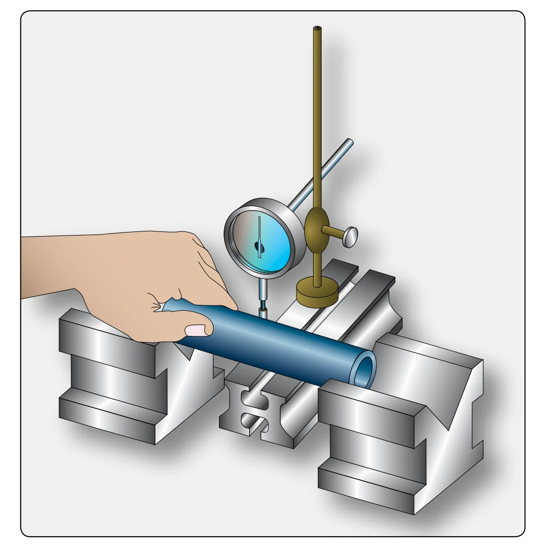
If the old piston is to be reused, or a new piston is to be used, measure the outside of the piston by means of a micrometer. Measurements must be taken in several directions and on the skirt, as well as on the lands section. Check these sizes against the cylinder size. Most engines use cam ground pistons to compensate for the greater expansion parallel to the pin during engine operation. The diameter of these pistons measures several thousandths of an inch larger at an angle to the piston pin hole, than parallel to the pin hole. Inspect the ring grooves for evidence of wear. The groove needs to be checked for side clearance with a feeler gauge to determine the amount of wear in the grooves. Examine the piston pin for scoring, cracks, excessive wear, and pitting. Check the clearance between the piston pin and the bore of the piston pin bosses using a telescopic gauge and a micrometer. Use the magnetic particle method to inspect the pin for cracks. Since the pins are often case hardened, cracks show up inside the pin more often than they do on the outside. Check the pin for bends using V-blocks and a dial indicator on a surface plate. [Figure 10-11] Measure the fit of the plugs in the pin. In many cases, the pistons and piston pins are routinely replaced at overhaul.
Valves & Valve Springs
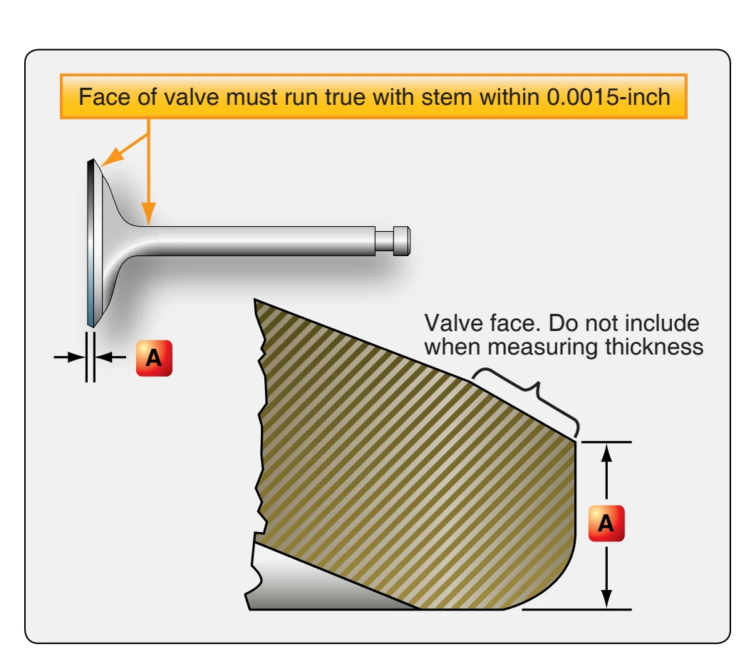
The locations for checking runout and edge thickness of the valves are shown in Figure 10-12. Measure the edge thickness of valve heads. If, after re-facing, the edge thickness is less than the limit specified by the manufacturer, the valve must not be re-used. The edge thickness can be measured with sufficient accuracy by a dial indicator and a surface plate.
Using a magnifying glass, examine the valve in the stem area and the tip for evidence of cracks, nicks, or other indications of damage. This type of damage seriously weakens the valve, making it susceptible to failure. If superficial nicks and scratches on the valve indicate that it might be cracked, inspect it using a structural inspection method described later. Examine the valve springs for cracks, rust, broken ends, and compression. Cracks can be located by visual inspection or the magnetic particle method.
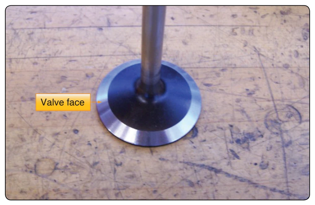
Critical areas of the valve include the face and tip [Figure 10-13], both of which should be examined for pitting and excessive wear. Minor pitting on valve faces can sometimes be removed by grinding.
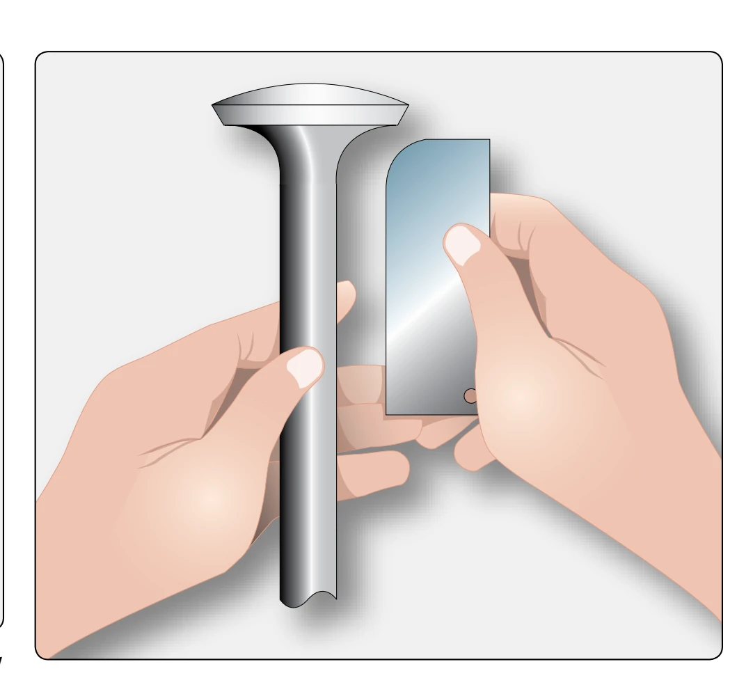
Inspect the valve for stretch and wear using a micrometer or a valve radius gauge. [Figure 10-14] If a micrometer is used, stretch is found as a smaller diameter of the valve stem near the neck of the valve. Measure the diameter of the valve stem and check the fit of the valve in its guide.
Examine the valve visually for physical damage and damage from burning or corrosion. Do not re-use valves that indicate damage of this nature.
Compression is tested with a valve spring compression tester. [Figure 10-15] The spring is compressed until its total height is that specified by the manufacturer. The dial on the tester should indicate the pressure, in pounds, required to compress
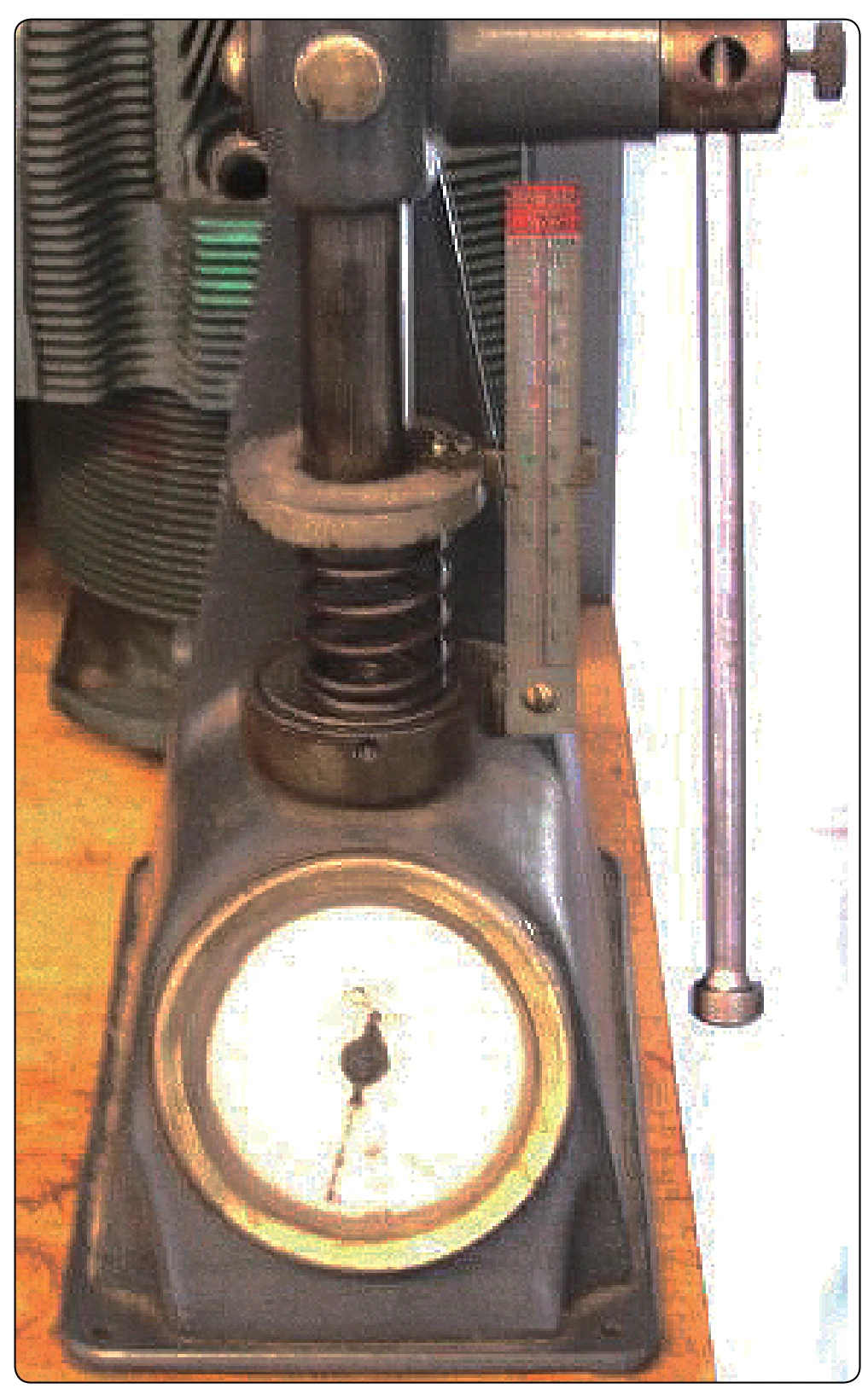
the spring to the specified height. This must be within the pressure limits established by the manufacturer.
Refacing Valve Seats
The valve seat inserts of aircraft engine cylinders usually are in need of refacing at every overhaul. They are refaced to provide a true, clean, and correct size seat for the valve. When valve guides or valve seats are replaced in a cylinder, the seats must be made concentric with the valve guide.
Low power engines can use either bronze or steel seats. Bronze seats, although not widely used on current engines, are made of aluminum bronze or phosphor bronze alloys. Steel seats are commonly used for valve seats on higher powered engines and are made of heat-resistant steel with a layer of stellite steel alloy on the valve contact surface. Stellite seats can require a special stone to grind this very hard material.
Steel valve seats are refaced by grinding equipment. [Figure 10-16] Bronze seats are refaced preferably by the use of cutters or reamers, but they may be ground when this equipment is not available. The only disadvantage of using a stone on bronze is that the soft metal loads the stone to such an extent that much time is consumed in redressing the stone to keep it clean.
The equipment used on steel seats can be either wet or dry valve seat grinding equipment. The wet grinder uses a mixture of soluble oil and water to wash away the chips and to keep the stone and seat cool; this produces a smoother, more accurate job than the dry grinder. The stones may be either silicon carbide or aluminum oxide.