
Chapter 3
Induction & Exhaust Systems
Induction & Exhau
Reciprocating Engine Induction Systems
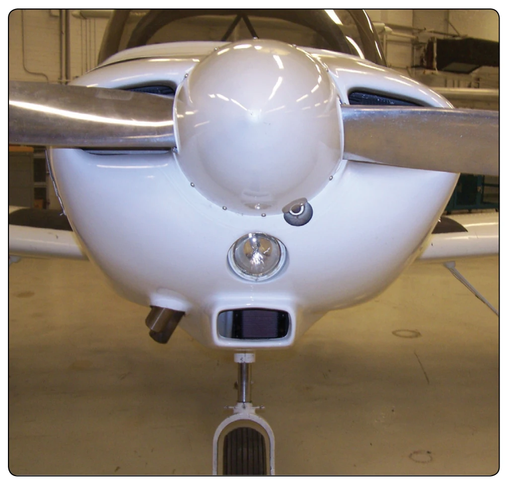
The basic induction system of an aircraft reciprocating engine consists of an air scoop used to collect the inlet air and ducting that transfers the air to the inlet filter. The air filter is generally housed in the carburetor heat box or other housing close by that is attached to the carburetor or fuel injection controller. The engine used in light aircraft is usually equipped with either a carburetor or a fuel-injection system. After air passes through the fuel metering device, an intake manifold with long curved pipes or passages is used to send the air-fuel mixture to the cylinders. An induction air scoop is shown in Figure 3-1. The air scoop is located on the engine cowling to allow maximum airflow into the engine’s induction system. The air filter, shown in Figure 3-2, prevents dirt and other foreign matter from entering the engine. Filtered air enters the fuel metering device (carburetor/fuel injector) where the throttle plate controls the amount of air flowing to the engine. The air coming out of the throttle is referred to as manifold pressure. This pressure is measured in inches of mercury ("Hg) and controls engine power output.
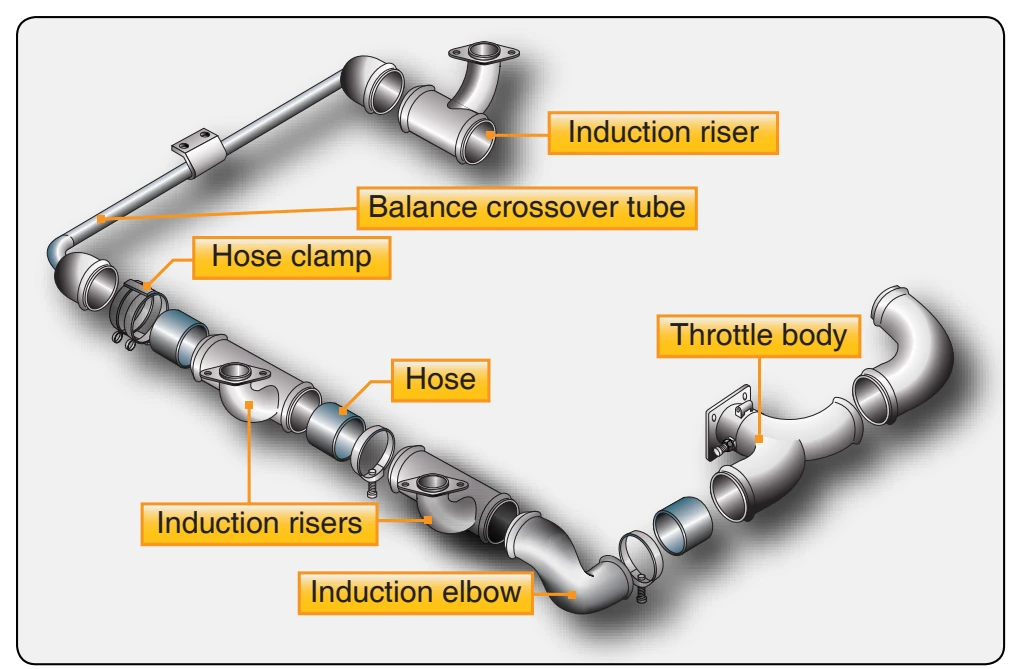
Induction systems can consist of several different arrangements. Two that are used are the updraft and downdraft induction systems. An updraft induction system consists of
ust Systems
two runners and a balance tube with intake pipes for each cylinder to deliver induction air to each cylinder’s intake port. [Figure 3-3] The balance tube is used to reduce pressure imbalances between the two side induction runners. With carbureted engines, it is important to maintain a constant and even pressure in the induction system so that each cylinder receives equal amounts of fuel. On fuel-injected engines, the fuel is injected at the intake port just before the intake valve. It is important with this system to keep the pressure consistent at each intake port.
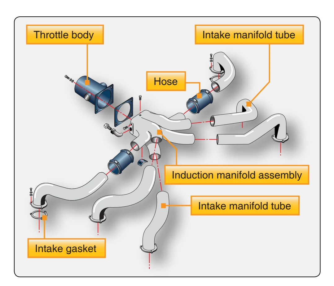
A downdraft balanced induction system provides optimum airflow to each of the individual cylinders throughout a wide operational range. [Figure 3-4] Better matched air-fuel ratios provide a much smoother and more efficient engine operation. Air from the induction manifold flows into the intake ports where it is mixed with fuel from the fuel nozzles and then enters the cylinders as a combustible mixture as the intake valve opens.
Basic Carburetor Induction System
Figure 3-2 is a diagram of an induction system used in an engine equipped with a carburetor. In this induction system, carburetor normal flow air is admitted at the lower front nose cowling below the propeller spinner and is passed through an air filter into air ducts leading to the carburetor. A carburetor heat air valve is located below the carburetor for selecting an alternate warm air source (carburetor heat) to prevent carburetor icing. [Figure 3-5] Carburetor icing occurs when the temperature is lowered in the throat of the carburetor and enough moisture is present to freeze and block the flow of air to the engine. The carburetor heat valve admits air from the outside air scoop for normal operation, and it admits warm air from the engine compartment for operation during icing conditions. The carburetor heat is operated by a push-pull control in the flight deck. When the carburetor heat air door is closed, warm ducted air from around the exhaust is directed into the carburetor. This raises the intake air temperature. An alternate air door can be opened by engine suction if the normal route of airflow should be blocked by something. The valve is spring loaded closed and is sucked open by the engine if needed.
The carburetor air filter, shown in Figure 3-6, is installed in the air scoop in front of the carburetor air duct. Its purpose is
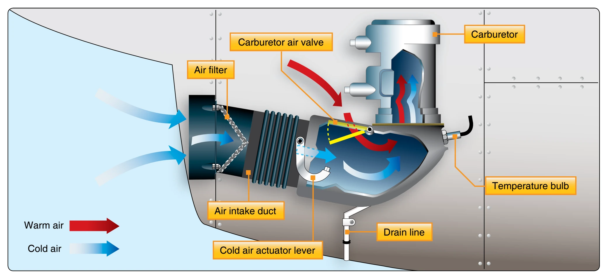
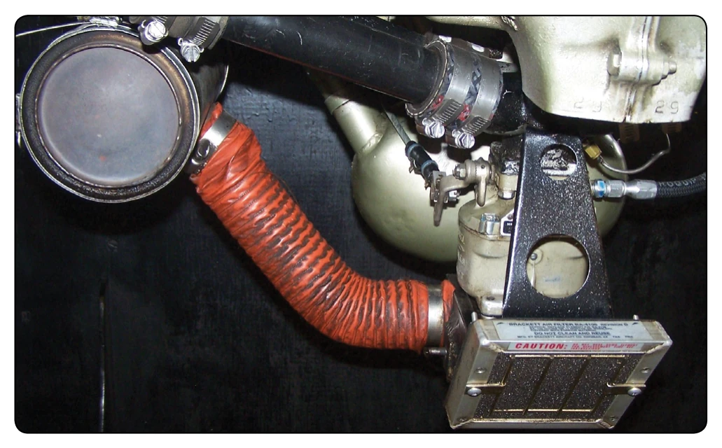
to stop dust and other foreign matter from entering the engine through the carburetor. The screen consists of an aluminum alloy frame and a deeply crimped screen, arranged to present maximum screen area to the airstream. There are several types of air filters in use including paper, foam, and other types of filters. Most air filters require servicing at regular intervals and the specific instructions for the type of filter must be followed. [Figure 3-6]
The carburetor air ducts consist of a fixed duct riveted to the nose cowling and a flexible duct between the fixed duct and the carburetor air valve housing. The carburetor air ducts normally provide a passage for outside air to the carburetor. Applying carburetor heat to an operating engine decreases the density of the air, which leans the air-fuel mixture. Air enters the system through the ram-air intake. The intake opening is located in the slipstream so the air is forced into the induction system giving a ram effect to the incoming airflow. The air passes through the air ducts to the carburetor. The carburetor meters the fuel in proportion to the air and mixes the air with
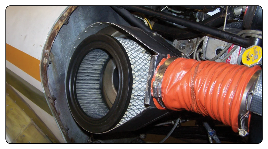
the correct amount of fuel. The throttle plate of the carburetor can be controlled from the flight deck to regulate the flow of air (manifold pressure), and in this way, power output of the engine can be controlled.
Although many newer aircraft are not so-equipped, some engines are equipped with carburetor air temperature indicating systems which shows the temperature of the air at the carburetor inlet. If the bulb is located at the engine side of the carburetor, the system measures the temperature of the air-fuel mixture.