
Chapter 3
Induction & Exhaust Systems
extinguisher while the aircraft engine is being started. This is a necessary precaution against fire during the starting procedure. The fireguard must be familiar with the induction system of the engine so that in case of fire, they can direct the CO into the air intake of the engine to extinguish it. A 2 fire could also occur in the exhaust system of the engine from liquid fuel being ignited in the cylinder and expelled during the normal rotation of the engine.
If an engine fire develops during the starting procedure, continue cranking to start the engine and blow out the fire. If the engine does not start and the fire continues to burn, discontinue the start attempt. The fireguard then extinguishes the fire using the available equipment. The fireguard must observe all safety practices at all times while standing by during the starting procedure.
Induction System Troubleshooting
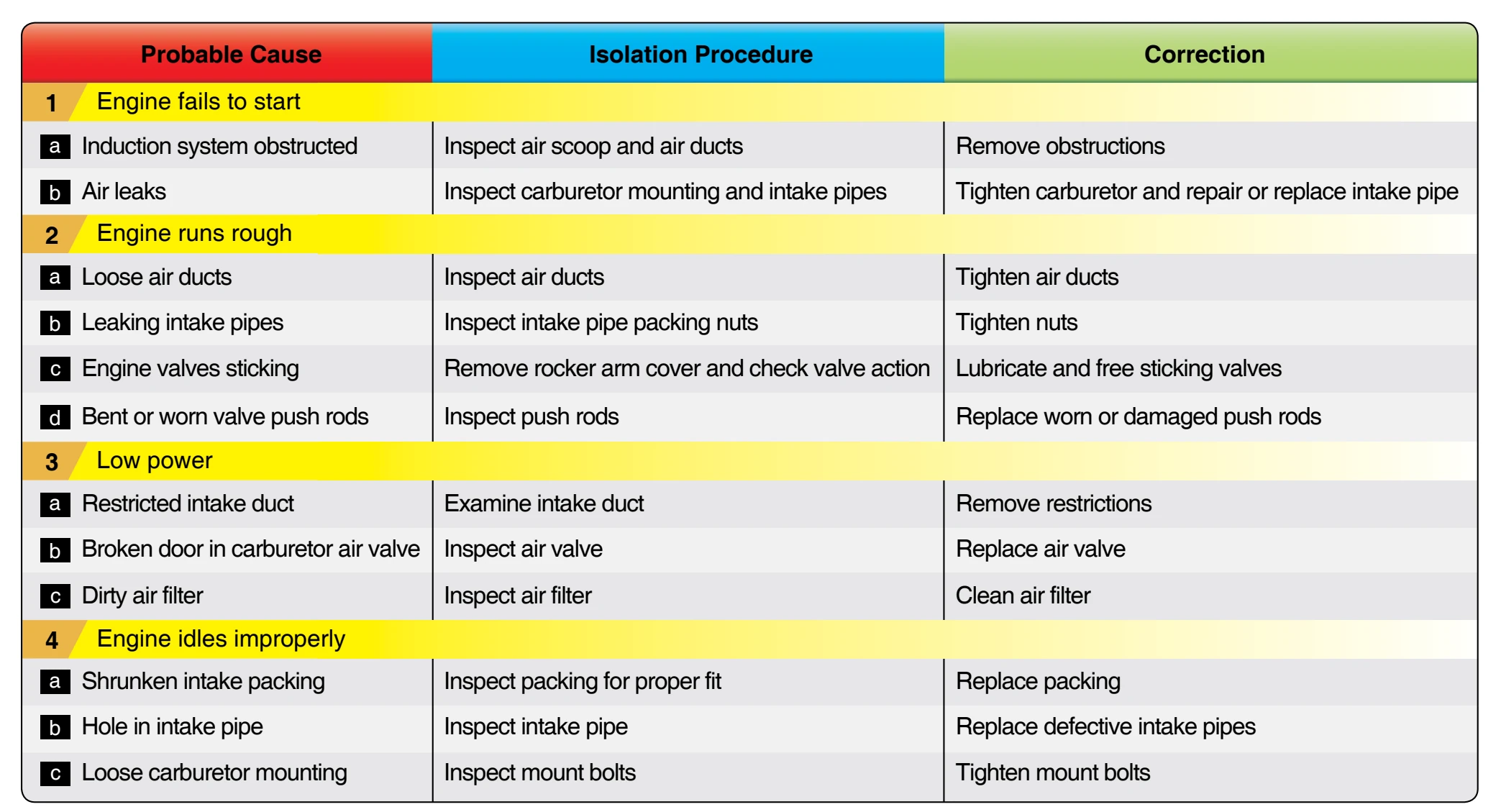
Figure 3-8 provides a general guide to the most common induction system troubles.
Supercharged Induction Systems
Since aircraft operate at altitudes where the air pressure is lower, it is useful to provide a system for compressing the air-fuel mixture. Some systems are used to normalize the air pressure entering the engine. These systems are used to regain the air pressure lost by the increase in altitude. This type of system is not a ground boost system and it is not used to ever boost the manifold pressure above 30 inches of mercury. A true supercharged engine, called ground boosted engines, can boost the manifold pressure above 30 inches of mercury. In other words, a true supercharger boosts the manifold pressure above ambient pressure.
Since many engines installed in light aircraft do not use any type of compressor or supercharging device, induction systems for reciprocating engines can be broadly classified as supercharged or nonsupercharged. [Figure 3-9] Supercharging systems used in reciprocating engine induction systems are normally classified as either internally driven or externally driven (turbosupercharged). Internally driven superchargers compress the air-fuel mixture after it leaves the carburetor, while externally driven superchargers (turbochargers) compress the air before it is mixed with the
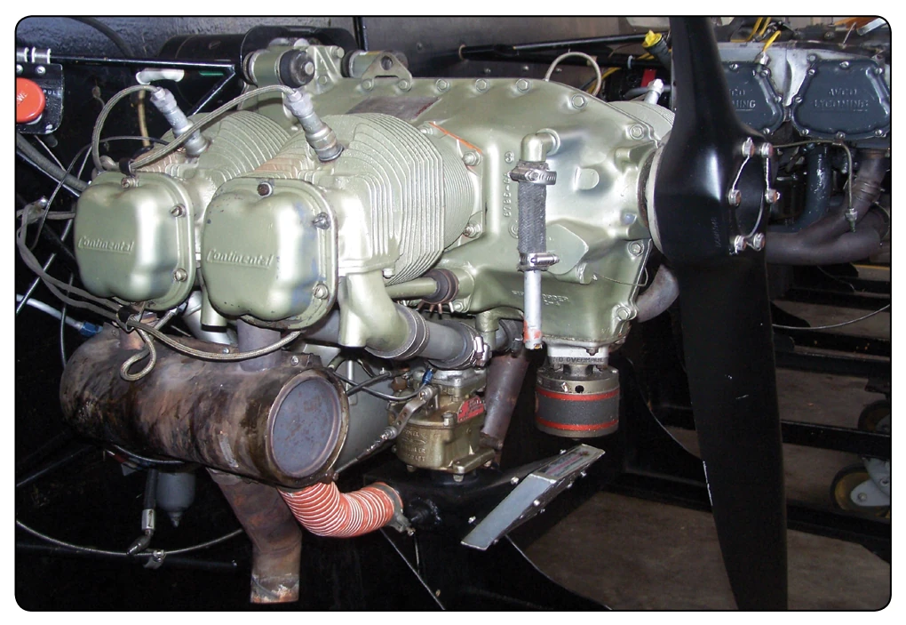
metered fuel from the carburetor.
Internally Driven Superchargers
Internally-driven superchargers were used almost exclusively in high horsepower radial reciprocating engines and are engine driven through a mechanical connection. Although their use is very limited, some are still used in cargo carriers and spray planes. Except for the construction and arrangement of the various types of superchargers, all induction systems with internally driven superchargers were very similar. Aircraft engines require the same air temperature control to produce good combustion in the engine cylinders. For example, the charge must be warm enough to ensure complete fuel vaporization and, thus, even distribution. At the same time, it must not be so hot that it reduces volumetric efficiency or causes detonation. All reciprocating engines must guard against intake air that is too hot. As with any type of supercharging (compressing intake air), the air gains heat as it is compressed. Sometimes this air requires cooling before it is routed to the engine’s intake ports. With these requirements, most induction systems that use internally driven superchargers must include pressure and temperaturesensing devices and the necessary units required to warm or cool the air.
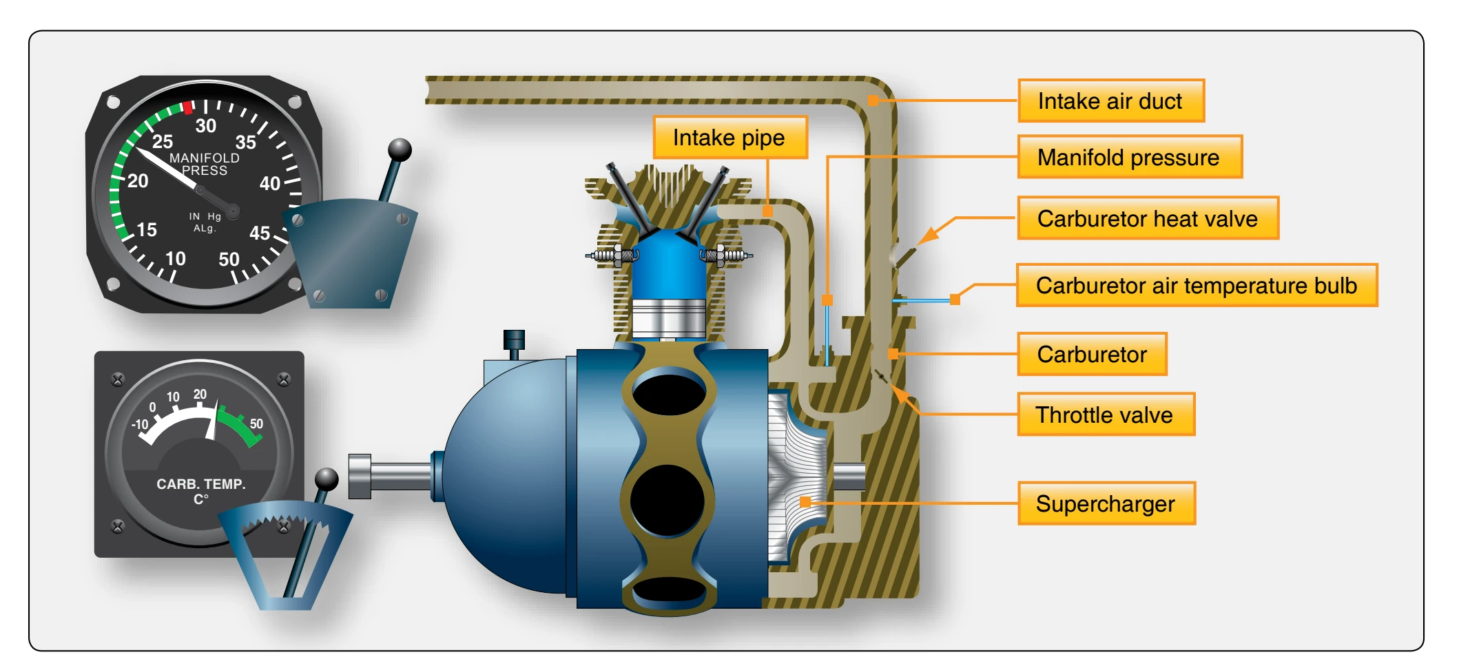
The simple internally driven supercharger induction system is used to explain the location of units and the path of the air and air-fuel mixture. [Figure 3-10] Air enters the system through the ram air intake. The intake opening is located so that the air is forced into the induction system, giving a ram effect caused by the aircraft moving through the air. The air passes through ducts to the carburetor. The carburetor meters the fuel in proportion to the air and mixes the air with the correct amount of fuel. The carburetor can be controlled from the flight deck to regulate the flow of air. In this way, the power output of the engine can be controlled. The manifold pressure gauge measures the pressure of the air-fuel mixture before it enters the cylinders. It is an indication of the performance that can be expected of the engine. The carburetor air temperature indicator measures either the temperature of the inlet air or of the air-fuel mixture. Either the air inlet or the mixture temperature indicator serves as a guide so that the temperature of the incoming charge may be kept within safe limits. If the temperature of the incoming air at the entrance to the carburetor scoop is 100 °F, there is approximately a 50 °F drop in temperature because of the partial vaporization of the fuel at the carburetor discharge nozzle. Partial vaporization takes place and the air temperature falls due to absorption of the heat by vaporization. The final vaporization takes place as the mixture enters the cylinders where higher temperatures exist. The fuel, as atomized into the airstream that flows in the induction system, is in a globular form. The problem, then, becomes one of uniformly breaking up and distributing the fuel, remaining in globular form to the various cylinders. On engines equipped with a large number of cylinders, the uniform distribution of the mixture becomes a greater problem, especially at high engine speeds when full advantage is taken of large air capacity.
One method used mainly on radial reciprocating engines of improving fuel distribution is shown in Figure 3-11. This device is known as a distribution impeller. The impeller is attached directly to the end of the rear shank of the crankshaft by bolts or studs. Since the impeller is attached to the end of the crankshaft and operates at the same speed, it does not materially boost or increase the pressure on the mixture
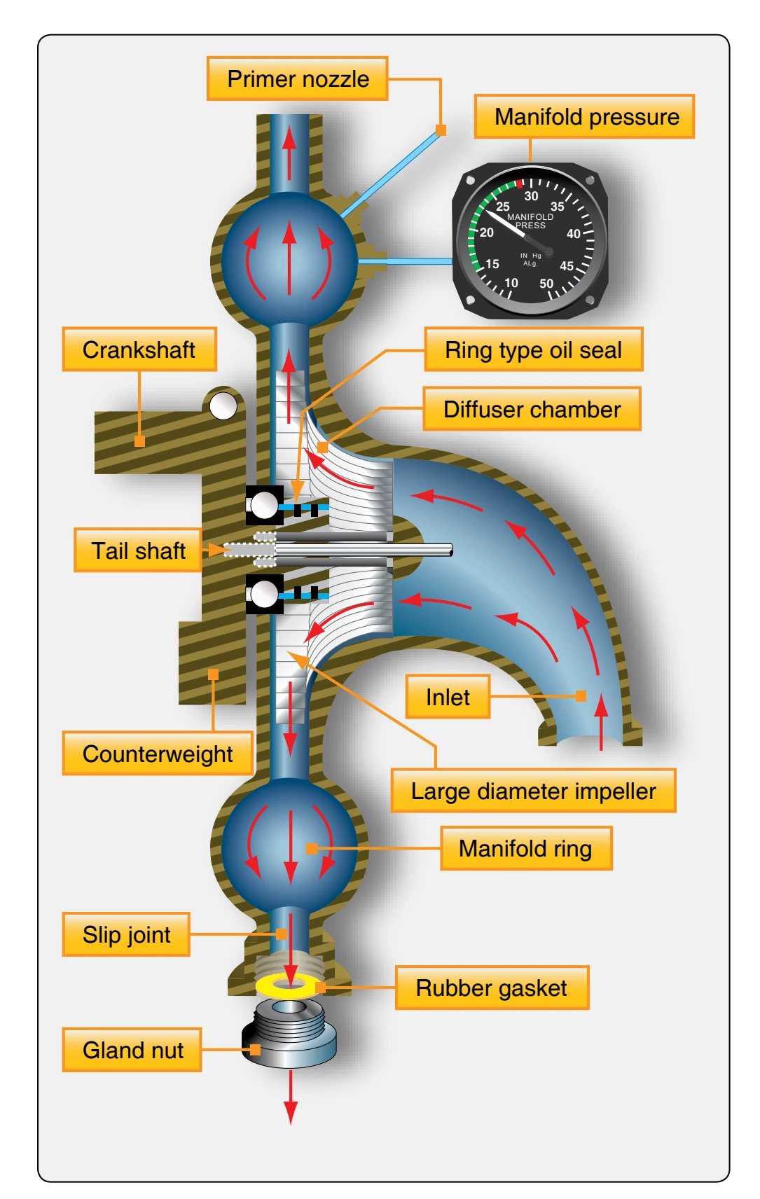
flowing into the cylinders. But, the fuel remaining in the globular form is broken up into finer particles as it strikes the impeller, thereby coming in contact with more air. This creates a more homogeneous mixture with a consequent improvement in distribution to the various cylinders, especially on acceleration of the engine or when low temperatures prevail.
To obtain greater pressure of the air-fuel mixture within the cylinders, the diffuser or blower section contains a high speed impeller. Unlike the distribution impeller, which is connected directly to the crankshaft, the supercharger, or blower impeller, is driven through a gear train from the crankshaft.
Turbosuperchargers
Externally driven superchargers (turbosuperchargers) are designed to deliver compressed air to the inlet of the carburetor or air-fuel control unit of an engine. Externally driven superchargers derive their power from the energy of engine exhaust gases directed against a turbine that drives an impeller that compresses the incoming air. For this reason, they are commonly called turbosuperchargers or turbochargers. To be a true supercharger, it must boost the manifold pressure above 30 "Hg.