
Chapter 3
Induction & Exhaust Systems
Afterburning/Thrust Augmentation
The terms afterburning and thrust augmentation generally pertain to military engine applications. The terms are used to describe the same system. Normally, this is used to increase the thrust of the engine up to double the original thrust. The required additions to the exhaust nozzle for this system are a flame stabilizer, fuel manifold, flame holder, igniter, and a
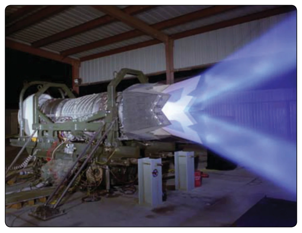
variable area exhaust nozzle. [Figure 3-50] After the engine has reached full power under normal operation, the power lever can be advanced to activate the afterburner. This allows more fuel to flow into the exhaust nozzle where it is ignited and burned. As energy and mass are added to the gas flow, the exhaust nozzle must open wider to allow greater flow. As the power lever is moved back out of the afterburner, the exhaust nozzle closes down again. Some low-bypass turbofan engines used in military aircraft use bypass (fan air) to flow into the exhaust nozzle. Just as in a ducted fan, this air is used in the afterburner. It contains more oxygen and assists combustion in the afterburner. Since fuel is being burned in the exhaust nozzle, the heat buildup around the nozzle is a problem. A special type of liner is used around the nozzle to allow cooler air to circulate around the nozzle. This operates somewhat like a single burner can combustion chamber. Operation in the afterburner mode is somewhat limited by high fuel consumption, which can be almost double normal consumption.
Thrust Vectoring
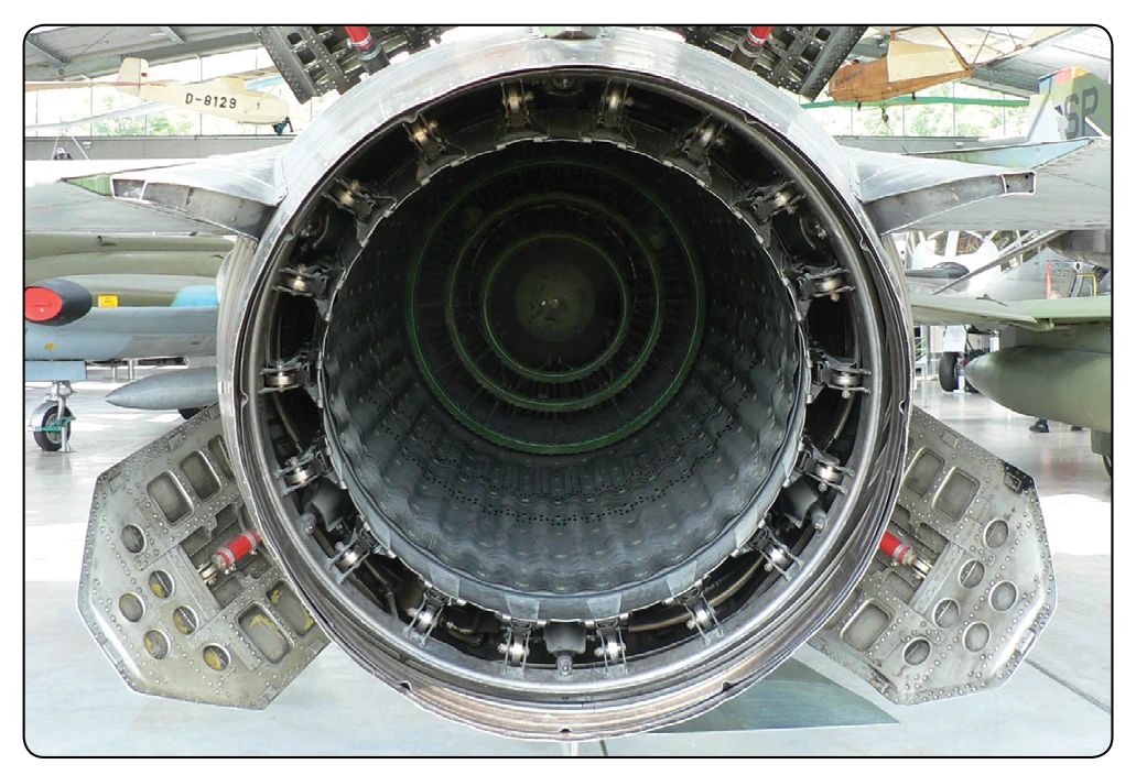
Thrust vectoring is the ability of an aircraft’s main engines to direct thrust other than parallel to the vehicle’s longitudinal axis, allowing the exhaust nozzle to move or change position to direct the thrust in varied directions. Vertical takeoff aircraft use thrust vectoring as takeoff thrust and then change direction to propel the aircraft in horizontal flight. Military aircraft use thrust vectoring for maneuvering in flight to change direction. Thrust vectoring is generally accomplished by relocating the direction of the exhaust nozzle to direct the thrust to move the aircraft in the desired path. At the rear of a gas turbine engine, a nozzle directs the flow of hot exhaust gases out of the engine and afterburner. Usually, the nozzle points straight out of the engine. The pilot can move, or vector, the vectoring nozzle up and down by 20°. This makes the aircraft much more maneuverable in flight. [Figure 3-51]
Engine Noise Suppression
Aircraft powered by gas turbine engines sometimes require noise suppression for the engine exhaust gases when operating from airports located in or near highly populated areas. Several types of noise suppressors are used. A common type of noise suppressor is an integral, airborne part of the aircraft engine installation or engine exhaust nozzle. Engine noise comes from several sources on the engine, the fan, or compressor and the air discharge from the core of the engine. There are three sources of noise involved in the operation of a gas turbine engine. The engine air intake and vibration from engine housing are sources of some noise, but the noise generated does not compare in magnitude with that produced by the engine exhaust. [Figure 3-52] The noise produced by the engine exhaust is caused by the high degree of turbulence of a high-velocity jet stream moving through a relatively quiet atmosphere. For a distance of a few nozzle diameters downstream behind the engine, the velocity of the jet stream is high, and there is little mixing of the atmosphere with the jet stream. In this region, the turbulence within the high speed jet stream is very fine grain turbulence and produces relatively high-frequency noise. This noise is caused by violent, turbulent mixing of the exhaust gases with the atmosphere and is influenced by the shearing action caused by the relative speeds between the velocity and the atmosphere.
Farther downstream, as the velocity of the jet stream slows down, the jet stream mixes with the atmosphere and turbulence of a coarser type begins. Compared with noise from other portions of the jet stream, noise from this portion has a much lower frequency. As the energy of the jet stream finally is dissipated in large turbulent swirls, a greater portion of the energy is converted into noise. The noise generated as the exhaust gases dissipate is at a frequency near the low end of the audible range. The lower the frequency of the noise,
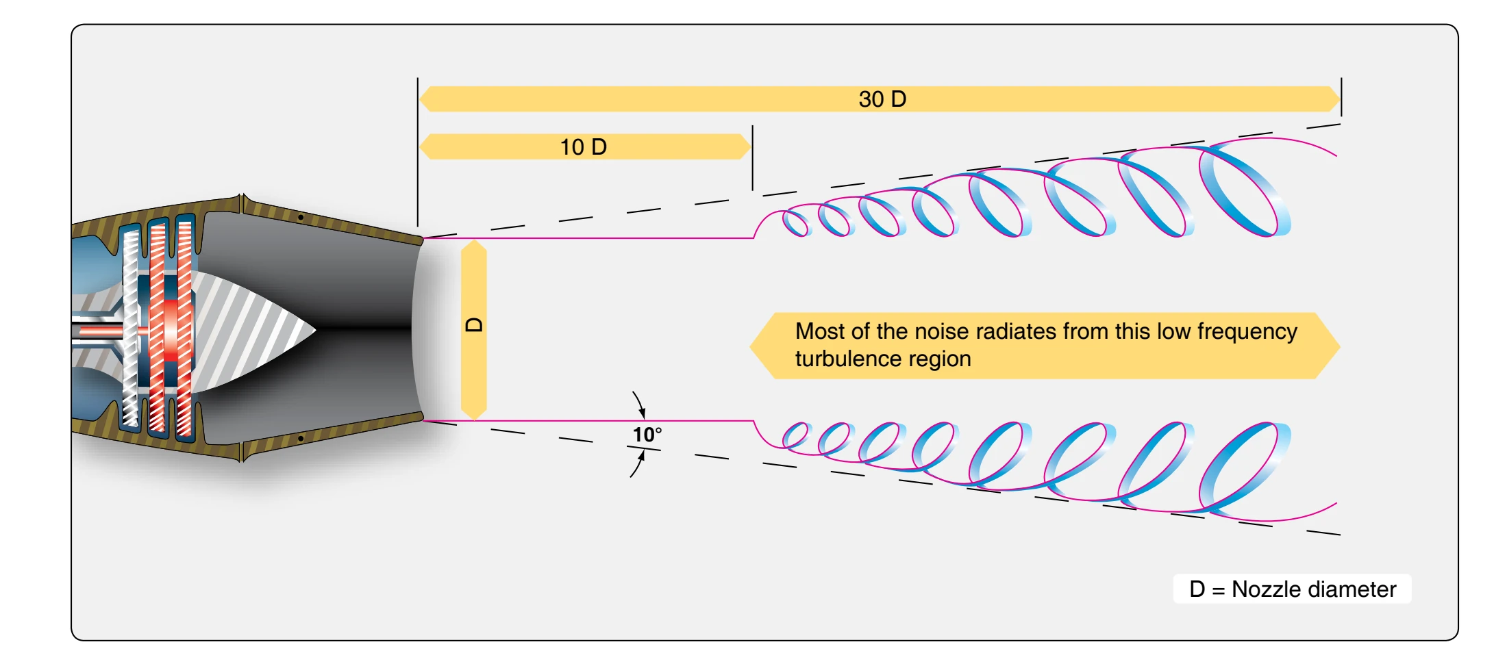
the greater the distance the noise travels. This means that the low-frequency noises reach an individual on the ground in greater volume than the high-frequency noises, and hence are more objectionable. High-frequency noise is weakened more rapidly than low-frequency noise, both by distance and the interference of buildings, terrain, and atmospheric disturbances. A deep-voiced, low-frequency foghorn, for example, may be heard much farther than a shrill, highfrequency whistle, even though both may have the same overall volume (decibels) at their source.
Noise levels vary with engine thrust and are proportional to the amount of work done by the engine on the air that passes through it. An engine having relatively low airflow but high thrust due to high turbine discharge (exhaust gas) temperature, pressure, and/or afterburning produces a gas stream of high velocity and, therefore, high noise levels. A larger engine, handling more air, is quieter at the same thrust and large engines operating at partial thrust are less noisy than smaller engines operating at full thrust. Thus, the noise level can be reduced considerably by operating the engine at lower power settings. Compared with a turbojet, a turbofan version of the same engine is quieter during takeoff. The noise level produced by a fan-type engine is lower, principally because the exhaust gas velocities ejected at the engine tailpipe are slower than those for a turbojet of comparative size.
Fan engines require a larger turbine to provide additional power to drive the fan. The large turbine, which usually has an additional turbine stage, reduces the velocity of the gas and, therefore, reduces the noise produced because exhaust gas noise is proportional to exhaust gas velocity. The exhaust from the fan is at a relatively low velocity and, therefore, does not create a noise problem. Because of the characteristic of low-frequency noise to linger at a relatively high volume, effective noise reduction for a turbojet aircraft must be achieved by revising the noise pattern or by changing the frequency of the noise emitted by the jet nozzle.
The noise suppressors in current use are either of the corrugatedperimeter type, or the multi-tube type. [Figure 3-53] Both types of suppressors break up the single, main jet exhaust stream into a number of smaller jet streams. This increases the total perimeter of the nozzle area and reduces the size of the air stream eddies created as the gases are discharged into the open air. Although the total noise-energy remains unchanged, the frequency is raised considerably. The size of the air stream eddies scales down at a linear rate with the size of the exhaust stream. This has two effects: 1) the change in frequency may put some of the noise above the audibility range of the human ear, and 2) high frequencies
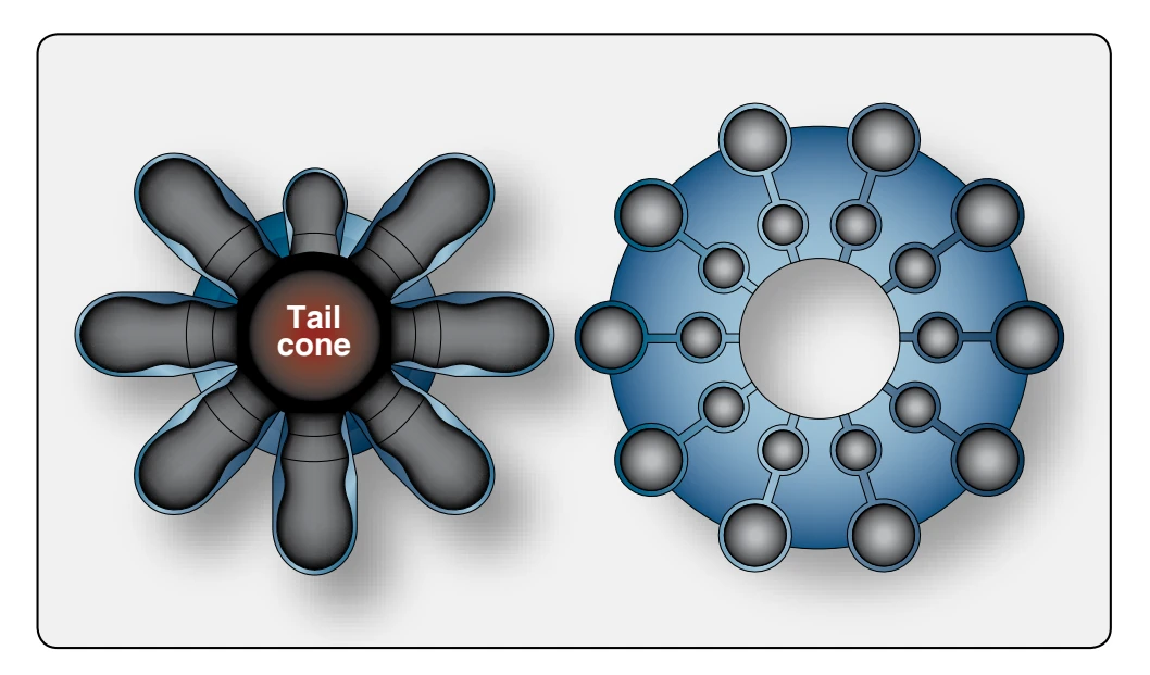
within the audible range, while perhaps more annoying, are more highly attenuated by atmospheric absorption than are low frequencies. Thus, the falloff in intensity is greater and the noise level is less at any given distance from the aircraft. In the engine nacelle, the area between the engine and the cowl has acoustic linings surrounding the engine. This noise-absorbing lining material converts acoustic energy into heat. These linings normally consist of a porous skin supported by a honeycomb backing and provide a separation between the face sheet and the engine duct. For optimum suppression, the acoustic properties of the skin and the liner are carefully matched.
Turbine Engine Emissions
Engineers are introducing new combustion technology that has dramatically reduced emissions from gas turbine engines. Lowering exhaust emissions from gas turbine, especially oxides of nitrogen (NO ), continue to require improvement. X Most of the research has centered around the combustion section of the engine. New technology with unique combustor design has greatly reduced emissions. One manufacturer has a design called the Twin Annular, Pre-mixing Swirler (TAPS) combustor. Most advanced designs rely on a method of pre-mixing the air-fuel before it enters the combustion burner area. In the TAPS design, air from the high-pressure compressor is directed into the combustor through two highenergy swirlers adjacent to the fuel nozzles. This swirl creates a more thorough and leaner mix of fuel and air, which burns at lower temperatures than in previous gas turbine engine designs. Most of the NO is formed by the reaction of oxygen X and nitrogen at high temperatures. The NO levels are higher X if the burning air-fuel mixture stays at high temperatures for a longer time. Newly designed combustors also produce lower levels of carbon monoxide and unburned hydrocarbons. The increases in gas turbine engine component efficiencies have resulted in fewer emissions from gas turbine engines.