
Chapter 3
Induction & Exhaust Systems
essentially a simple, stainless steel, conical or cylindrical pipe. The assembly also includes an engine tail cone and the struts inside the duct. The tail cone and the struts add strength to the duct, impart an axial direction to the gas flow, and smooth the gas flow. In a typical installation, the tailpipe assembly is mounted in the nacelle and attached at its forward end to the firewall. The forward section of the tailpipe is funnel shaped and surrounds but does not contact the turbine exhaust section. This arrangement forms an annular gap that serves as an air ejector for the air surrounding the engine hot section. As the high-velocity exhaust gases enter the tailpipe, a low-pressure effect is produced which causes the air around the engine hot section to flow through the annular gap into the tailpipe. The rear section of the tailpipe is secured to the airframe by two support arms, one on each side of the tailpipe. The support arms are attached to the upper surface of the wing in such

a way that allow movement fore and aft to compensate for expansion. The tailpipe assembly is wrapped in an insulating blanket to shield the surrounding area from the high heat produced by the exhaust gases. Such blankets may be made of a stainless steel laminated sheet on the outside and fiberglass on the inside. This is used when the engine exhaust is located some distance from the edge of the wing or aircraft structure.
Immediately aft of the turbine outlet, and usually just forward of the flange to which the exhaust duct is attached, the engine is instrumented for turbine discharge pressure. One or more pressure probes are inserted into the exhaust duct to provide adequate sampling of the exhaust gases. In large engines, it is not practical to measure the internal temperature at the turbine inlet, so the engine is often also instrumented for exhaust gas temperature at the turbine outlet.
Convergent Exhaust Nozzle
As the exhaust gases exit the rear of the engine, they flow into the exhaust nozzle. [Figure 3-46] The very first part of the exhaust nozzle and the exhaust plug form a divergent duct to reduce turbulence in the airflow, then the exhaust gases flow into the convergent component of the exhaust nozzle where the flow is restricted by a smaller outlet opening. Since this forms a convergent duct, the gas velocity is increased providing increased thrust. The restriction of the opening of the outlet of the exhaust nozzle is limited by two factors. If the nozzle opening is too big, thrust is being wasted. If it is too little, the flow is choked in the other components of the engine. In other words, the exhaust nozzle acts as an orifice, the size of which determines the density and velocity of the gases as they emerge from the engine. This is critical to thrust performance. Adjusting the area of the exhaust nozzle changes both the engine performance and the exhaust gas temperature. When the velocity of the exhaust gases at the
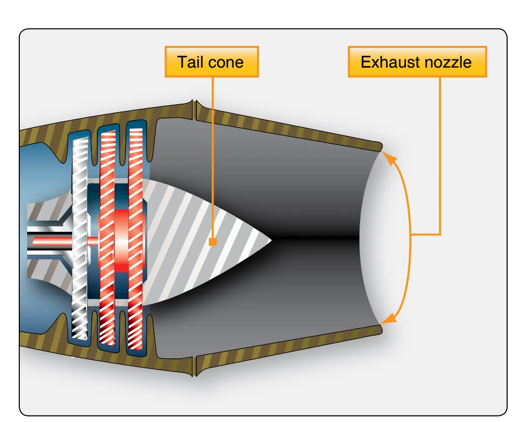
nozzle opening becomes Mach 1, the flow passes only at this speed—it does not increase or decrease. Sufficient flow to maintain Mach 1 at the nozzle opening and have extra flow (flow that is being restricted by the opening) creates what is called a choked nozzle. The extra flow builds up pressure in the nozzle, which is sometimes called pressure thrust. A differential in pressure exists between the inside of the nozzle and the ambient air. By multiplying this difference in pressure times the area of the nozzle opening, pressure thrust can be calculated. Many engines cannot develop pressure thrust because most of the energy is used to drive turbines that turn propellers, large fans, or helicopter rotors.
Convergent-Divergent Exhaust Nozzle
Whenever the engine pressure ratio is high enough to produce exhaust gas velocities which might exceed Mach 1 at the engine exhaust nozzle, more thrust can be gained by using a convergent-divergent type of nozzle. [Figure 3-47] The advantage of a convergent-divergent nozzle is greatest at high Mach numbers because of the resulting higher pressure ratio across the engine exhaust nozzle.
To ensure that a constant weight or volume of a gas flows past any given point after sonic velocity is reached, the rear part of a supersonic exhaust duct is enlarged to accommodate the additional weight or volume of a gas that flows at supersonic rates. If this is not done, the nozzle does not operate efficiently. This is the divergent section of the exhaust duct.
When a divergent duct is used in combination with a conventional exhaust duct, it is called a convergent-divergent exhaust duct. In the convergent-divergent, or C-D nozzle, the convergent section is designed to handle the gases while they remain subsonic, and to deliver the gases to the throat of the nozzle just as they attain sonic velocity. The divergent section
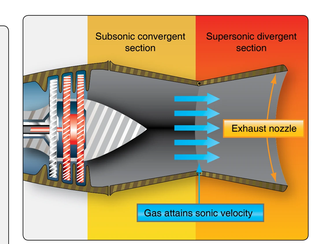
handles the gases, further increasing their velocity, after they emerge from the throat and become supersonic. As the gas flows from the throat of the nozzle, it becomes supersonic (Mach 1 and above) and then passes into the divergent section of the nozzle. Since it is supersonic, it continues to increase in velocity. This type of nozzle is generally used on very high speed aerospace vehicles.
Thrust Reversers
As aircraft have increased in gross weights with higher landing airspeeds, the problem of stopping an aircraft after landing has greatly increased. In many instances, the aircraft brakes can no longer be relied upon solely to slow the aircraft within a reasonable distance, immediately after touchdown. Most thrust reverser systems can be divided into two categories: mechanical-blockage and aerodynamic-blockage. Mechanical blockage is accomplished by placing a removable obstruction in the exhaust gas stream, usually somewhat to the rear of the nozzle. The engine exhaust gases are mechanically blocked and diverted at a suitable angle in the reverse direction by an inverted cone, half-sphere, or clam shell. [Figure 3-48] This is placed in position to reverse the flow of exhaust gases. This type is generally used with ducted turbofan engines, where the fan and core flow mix in a common nozzle before exiting the engine. The clamshell-type or mechanicalblockage reverser operates to form a barrier in the path of escaping exhaust gases, which nullifies and reverses the forward thrust of the engine. The reverser system must be able to withstand high temperatures, be mechanically strong, relatively light in weight, reliable, and “fail-safe.” When not in use, it must be streamlined into the configuration of the engine nacelle. When the reverser is not in use, the clamshell doors retract and nest neatly around the engine exhaust duct, usually forming the rear section of the engine nacelle.
In the aerodynamic blockage type of thrust reverser, used mainly with unducted turbofan engines, only fan air is used to slow the aircraft. A modern aerodynamic thrust reverser system consists of a translating cowl, blocker doors, and cascade vanes that redirect the fan airflow to slow the aircraft. [Figure 3-49] If the thrust levers are at idle position and the aircraft has weight on the wheels, moving the thrust levers aft activates the translating cowl to open, closing the blocker doors. This action stops the fan airflow from going aft and redirects it through the cascade vanes, which direct the airflow forward to slow the aircraft. Since the fan can produce approximately 80 percent of the engine’s thrust, the fan is the best source for reverse thrust. By returning the thrust levers (power levers) to the idle position, the blocker doors open and the translating cowl closes.
A thrust reverser must not have any adverse effect on engine operation either deployed or stowed. Generally, there is
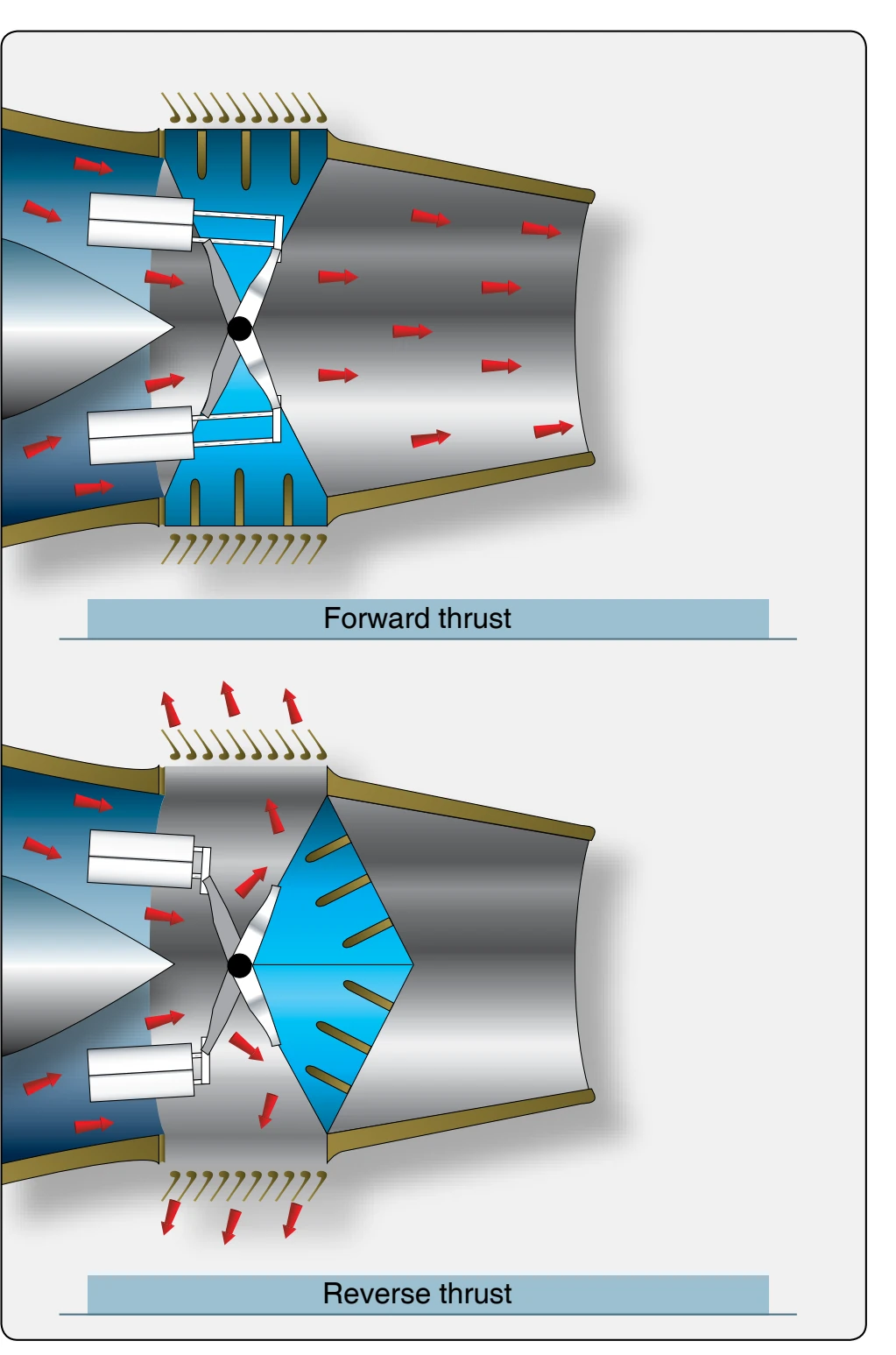
an indication in the flight deck with regard to the status of the reverser system. The thrust reverser system consists of several components that move either the clam shell doors or the blocker door and translating cowl. Actuating power is generally pneumatic or hydraulic and uses gearboxes, flexdrives, screwjacks, control valves, and air or hydraulic motors to deploy or stow the thrust reverser systems. The systems are locked in the stowed position until commanded to deploy by the flight deck. Since there are several moving parts, maintenance and inspection requirements are very important. While performing any type of maintenance, the reverser system must be mechanically locked out from deploying while personnel are in the area of the reverser system.