Chapter 3
Induction & Exhaust Systems
During the inspection of an exhaust system, close attention should be given to all external surfaces of the exhaust system for cracks, dents, or missing parts. This also applies to welds, clamps, supports, support attachment lugs, bracing, slip joints, stack flanges, gaskets, and flexible couplings. Each bend should be examined, as well as areas adjacent to welds. Any dented areas or low spots in the system should be inspected for thinning and pitting due to internal erosion by combustion products or accumulated moisture. An ice pick or similar pointed instrument is useful in probing suspected areas.
The system should be disassembled as necessary to inspect internal baffles or diffusers. If a component of the exhaust system is inaccessible for a thorough visual inspection or is hidden by nonremovable parts, it should be removed and checked for possible leaks. This can often be accomplished best by plugging the openings of the component, applying a suitable internal pressure (approximately 2 psi), and submerging it in water. Any leaks cause bubbles that can readily be detected. The procedures required for an installation inspection are also performed during most regular inspections. Daily inspection of the exhaust system usually consists of checking the exposed exhaust system for cracks, scaling, excessive leakage, and loose clamps.
Muffler & Heat Exchanger Failures
Approximately half of all muffler and heat exchanger failures can be traced to cracks or ruptures in the heat exchanger surfaces used for cabin and carburetor heat sources. Failures in the heat exchanger surface (usually in the outer wall) allow exhaust gases to escape directly into the cabin heat system. These failures, in most cases, are caused by thermal and vibration fatigue cracking in areas of stress concentration. Failure of the spot-welds, which attach the heat transfer pins, can result in exhaust gas leakage. In addition to a carbon monoxide hazard, failure of heat exchanger surfaces can permit exhaust gases to be drawn into the engine induction system, causing engine overheating and power loss.
Exhaust Manifold & Stack Failures
Exhaust manifold and stack failures are usually fatigue failures at welded or clamped points (e.g., stack-to-flange, stack-to-manifold, and crossover pipe or muffler connections). Although these failures are primarily fire hazards, they also present carbon monoxide problems. Exhaust gases can enter the cabin via defective or inadequate seals at firewall openings, wing strut fittings, doors, and wing root openings.
Internal Muffler Failures
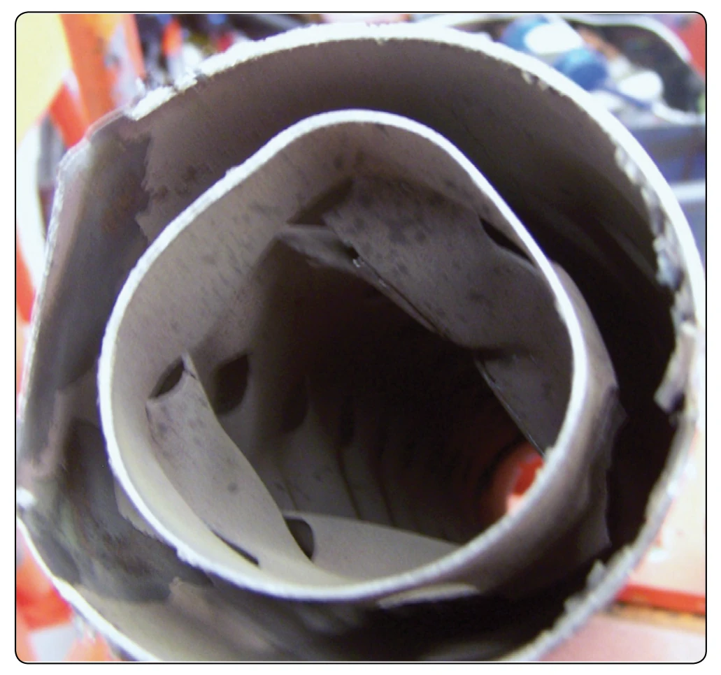
Internal failures (baffles, diffusers, etc.) can cause partial or complete engine power loss by restricting the flow of the exhaust gases. If pieces of the internal baffling breaks loose and partially or totally blocks the flow of exhaust gases, engine failure can occur. [Figure 3-43] As opposed to other failures, erosion and carburization caused by the extreme thermal conditions are the primary causes of internal failures. Engine backfiring and combustion of unburned fuel within the exhaust system are probable contributing factors. In addition, local hot-spot areas caused by uneven exhaust gas flow can result in burning, bulging, or rupture of the outer muffler wall.
Exhaust Systems with Turbocharger
When a turbocharger or a turbosupercharger system is included, the engine exhaust system operates under greatly increased pressure and temperature conditions. Extra precautions should be taken in exhaust system care and maintenance. During high-pressure altitude operation, the exhaust system pressure is maintained at or near sea level values. Due to the pressure differential, any leaks in the system allow the exhaust gases to escape with torch-like intensity that can severely damage adjacent structures. A common cause of malfunction is coke deposits (carbon buildup) in the waste gate unit causing erratic system operation. Excessive deposit buildups may cause the waste gate valve to stick in the “closed” position, causing an overboost condition. Coke deposit buildup in the turbo itself causes a gradual loss of power in flight and low manifold pressure reading prior to takeoff. Experience has shown that periodic de-coking, or removal of carbon deposits, is necessary to maintain peak efficiency. Clean, repair, overhaul, and adjust the system components and controls in accordance with the applicable manufacturer’s instructions.
Augmentor Exhaust System
On exhaust systems equipped with augmentor tubes, the augmentor tubes should be inspected at regular intervals for proper alignment, security of attachment, and general overall condition. Even where augmentor tubes do not contain heat exchanger surfaces, they should be inspected for cracks along with the remainder of the exhaust system. Cracks in augmentor tubes can present a fire or carbon monoxide hazard by allowing exhaust gases to enter the nacelle, wing, or cabin areas.
Exhaust System Repairs
It is generally recommended that exhaust stacks, mufflers, tailpipes, etc., be replaced with new or reconditioned components rather than repaired. Welded repairs to exhaust systems are complicated by the difficulty of accurately identifying the base metal so that the proper repair materials can be selected. Changes in composition and grain structure of the original base metal further complicate the repair. However, when welded repairs are necessary, the original contours should be retained; the exhaust system alignment must not be warped or otherwise affected. Repairs or sloppy weld beads that protrude internally are not acceptable as they cause local hot spots and may restrict exhaust gas flow. The proper hardware and clamps should always be used when repairing or replacing exhaust system components. Steel or low temperature, self-locking nuts should not be substituted for brass or special high temperature locknuts used by the manufacturer. Old gaskets should never be re-used. When disassembly is necessary, gaskets should be replaced with new ones of the same type provided by the manufacturer.
Turbine Engine Exhaust Nozzles
Turbine engines have several different types of exhaust nozzles depending upon the type of engine. Turboshaft engines in helicopters can have an exhaust nozzle that forms a divergent duct. This type of nozzle would not provide any thrust, all engine power going to rotate the rotors, improving helicopter hovering abilities. Turbofan engines tend to fall into either ducted fan of unducted fan engines. Ducted fan engines take the fan airflow and direct it through closed ducts along the engine. Then, it flows into a common exhaust nozzle. The core exhaust flow and the fan flow mix and flow from the engine through this mixed nozzle. The unducted fan has two nozzles, one for the fan airflow and one for the core airflow. These both flow to ambient air separate from each other and have separate nozzles. [Figure 3-44]
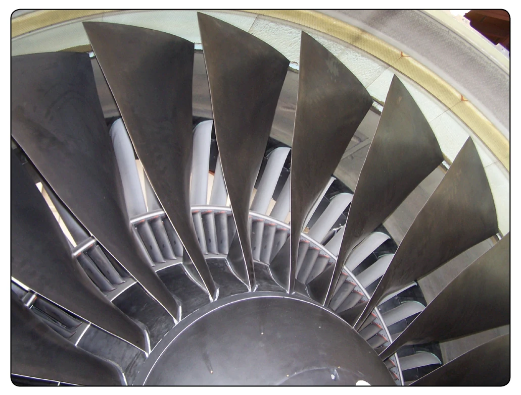
The unducted engine or the separate nozzle engine handles high amounts of airflow. The fan air which creates most of the thrust (80–85 percent total thrust) must be directed through the fan blades and exit vanes with little turbulence as possible. [Figure 3-45] The core airflow needs to be straightened as it comes from the turbine. Through the use of a converging nozzle, the exhaust gases increase in velocity before they are discharged from the exhaust nozzle. Increasing the velocity of the gases increases their momentum and increases the thrust produced (20–15 percent total thrust). Most of the energy of the gases have been absorbed to drive the fan through the low-pressure turbine stages.
Turboprop exhaust nozzles provide small amounts of thrust (10–15 percent) but are mainly used to discharge the exhaust gases from the aircraft. Most of the energy has been transferred to the propeller. On some turboprop aircraft, an exhaust duct is often referred to as a tailpipe, although the duct itself is