Chapter 5
Engine Starting Systems
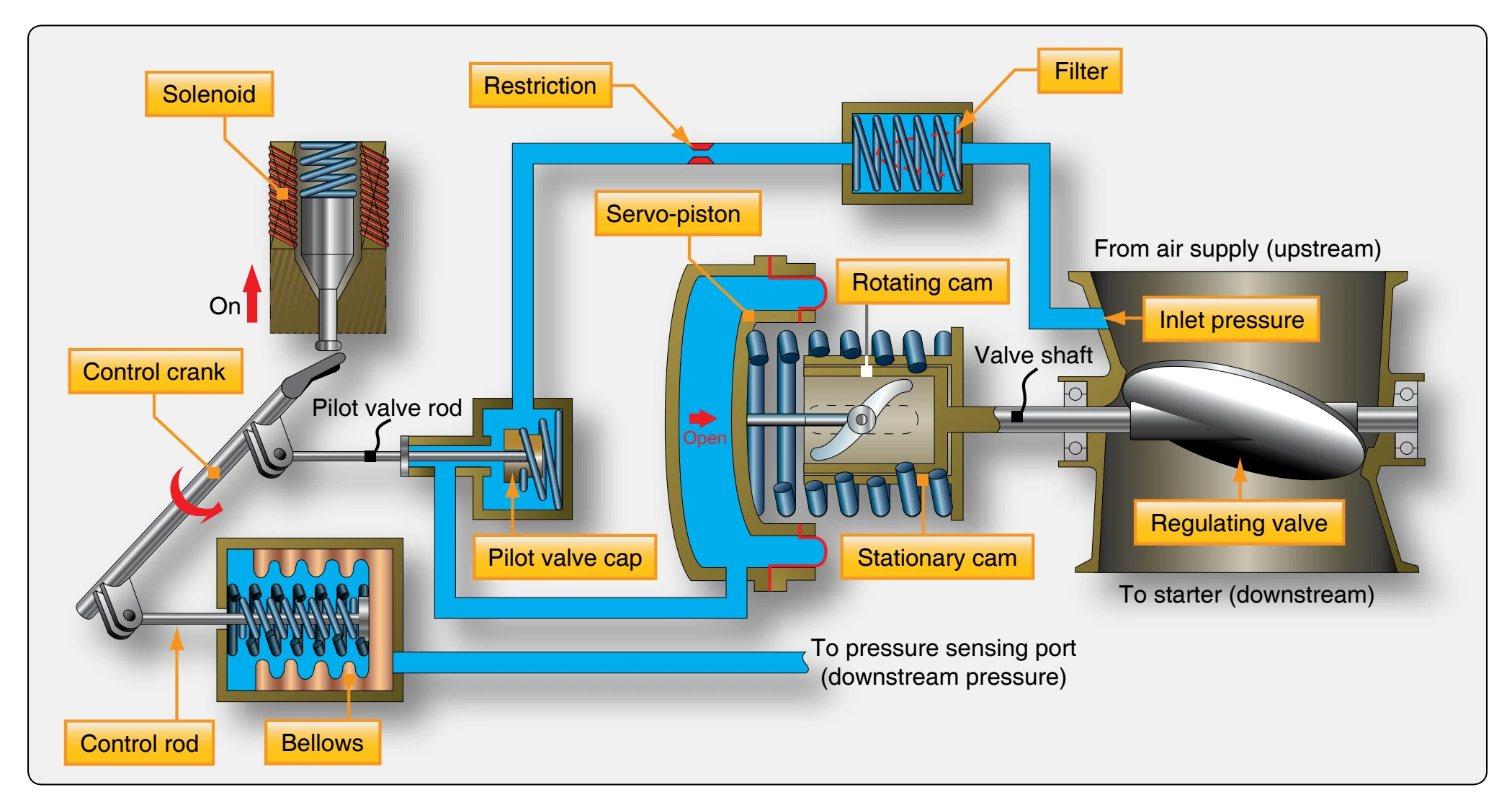
Turning on the starter switch energizes the regulating valve solenoid. The solenoid retracts and allows the control crank to rotate to the open position. The control crank is rotated by the control rod spring moving the control rod against the closed end of the bellows. Since the regulating valve is closed and downstream pressure is negligible, the bellows can be fully extended by the bellows spring.
As the control crank rotates to the open position, it causes the pilot valve rod to open the pilot valve, allowing upstream air, which is supplied to the pilot valve through a suitable filter and a restriction in the housing, to flow into the servo piston chamber. The drain side of the pilot valve, which bleeds the servo chamber to the atmosphere, is now closed by the pilot valve rod and the servo piston moves inboard. [Figure 5-24] This linear motion of the servo piston is translated to rotary motion of the valve shaft by the rotating cam, thus opening the regulating valve. As the valve opens, downstream pressure increases. This pressure is bled back to the bellows through the pressure-sensing line and compresses the bellows. This action moves the control rod, thereby turning the control crank, and moving the pilot valve rod gradually away from the servo chamber to vent to the atmosphere. [Figure 5-24] When downstream (regulated) pressure reaches a preset value, the amount of air flowing into the servo through the restriction equals the amount of air being bled to the atmosphere through the servo bleed; the system is in a state of equilibrium.
When the bleed valve and the start valve are open, the regulated air passing through the inlet housing of the starter
impinges on the turbine causing it to turn. As the turbine turns, the gear train is activated and the inboard clutch gear, which is threaded onto a helical screw, moves forward as it rotates; its jaw teeth engage those of the outboard clutch gear to drive the output shaft of the starter. The clutch is an overrunning type to facilitate positive engagement and minimize chatter. When starter cut-out speed is reached, the start valve is closed. When the air to the starter is terminated, the outboard clutch gear, driven by the engine, begins to turn faster than the inboard clutch gear; the inboard clutch gear, actuated by the return spring, disengages the outboard clutch gear allowing the rotor to coast to a halt. The outboard clutch shaft continues to turn with the engine.
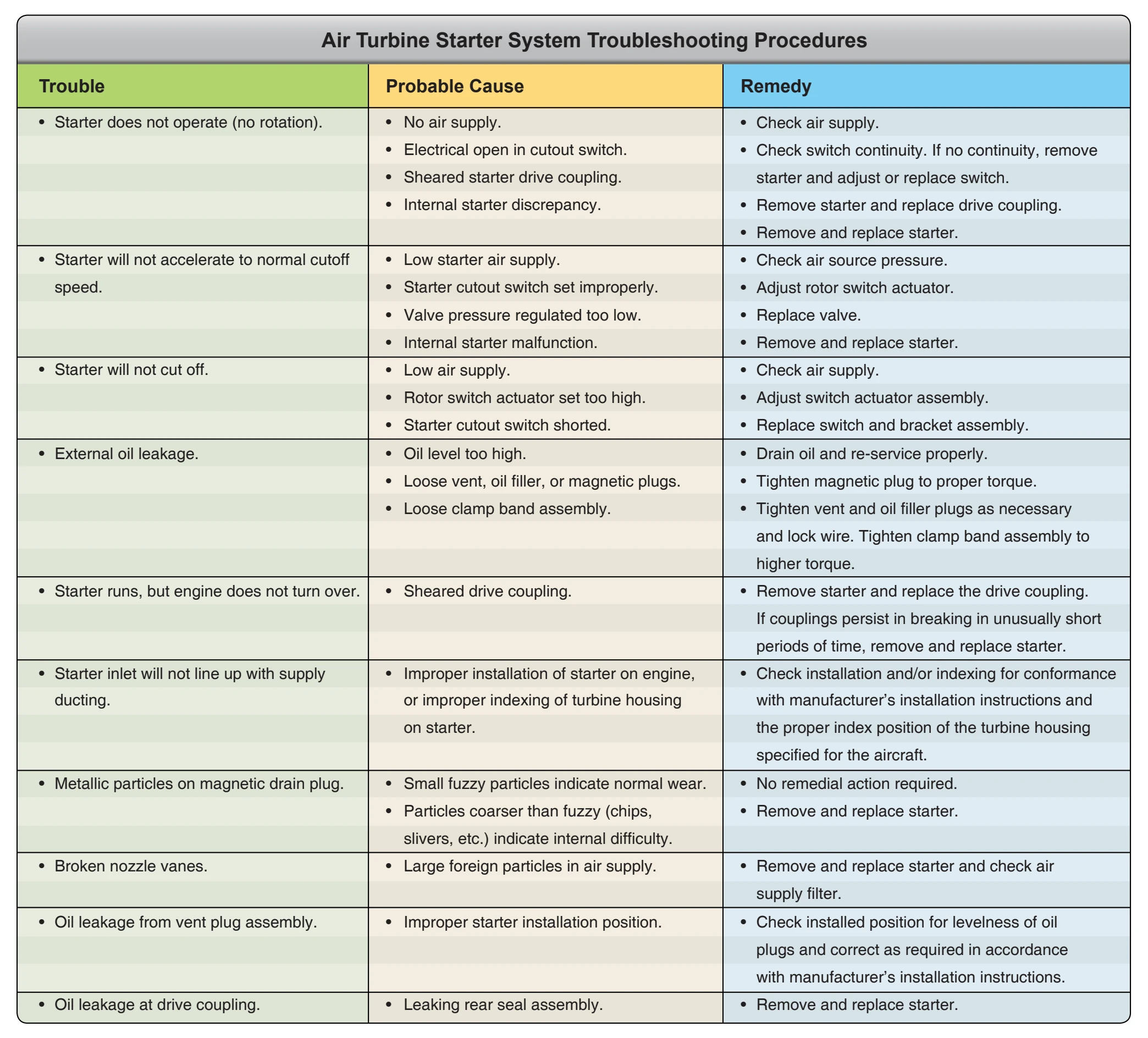
Air Turbine Starter Troubleshooting Guide
The troubleshooting procedures listed in Figure 5-25 are applicable to air turbine starting systems equipped with a combination pressure-regulating and shutoff valve. These procedures should be used as a guide only and are not intended to replace the manufacturer’s instructions.