
Chapter 5
Engine Starting Systems
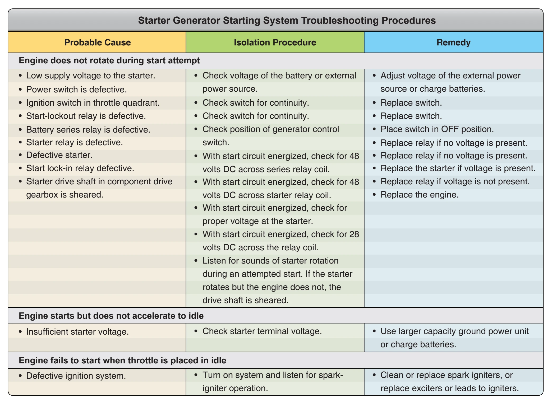
Troubleshooting a Starter Generator Starting System
The procedures listed in Figure 5-19 are typical of those used to repair malfunctions in a starter generator starting system similar to the system described in this section. These procedures are presented as a guide only. The appropriate manufacturer’s instructions and approved maintenance directives should always be consulted for the aircraft involved.
Air Turbine Starters
Air turbine starters are designed to provide high starting torque from a small, lightweight source. The typical air turbine starter weighs from one-fourth to one-half as much as an electric starter capable of starting the same engine. It is capable of developing considerable more torque than the electric starter.
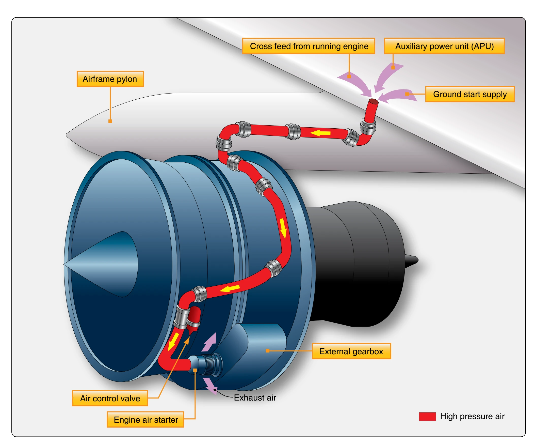
The typical air turbine starter consists of an axial flow turbine that turns a drive coupling through a reduction gear train and a starter clutch mechanism. The air to operate an air turbine starter is supplied from either a ground-operated air cart, the APU, or a cross-bleed start from an engine already operating.
[Figure 5-20] Only one source of around 30–50 pounds per square inch (psi) is used at a time to start the engines. The pressure in the ducts must be high enough to provide for a complete start with a normal limit minimum of about 30 psi. When starting engines with an air turbine starter, always check the duct pressure prior to the start attempt.
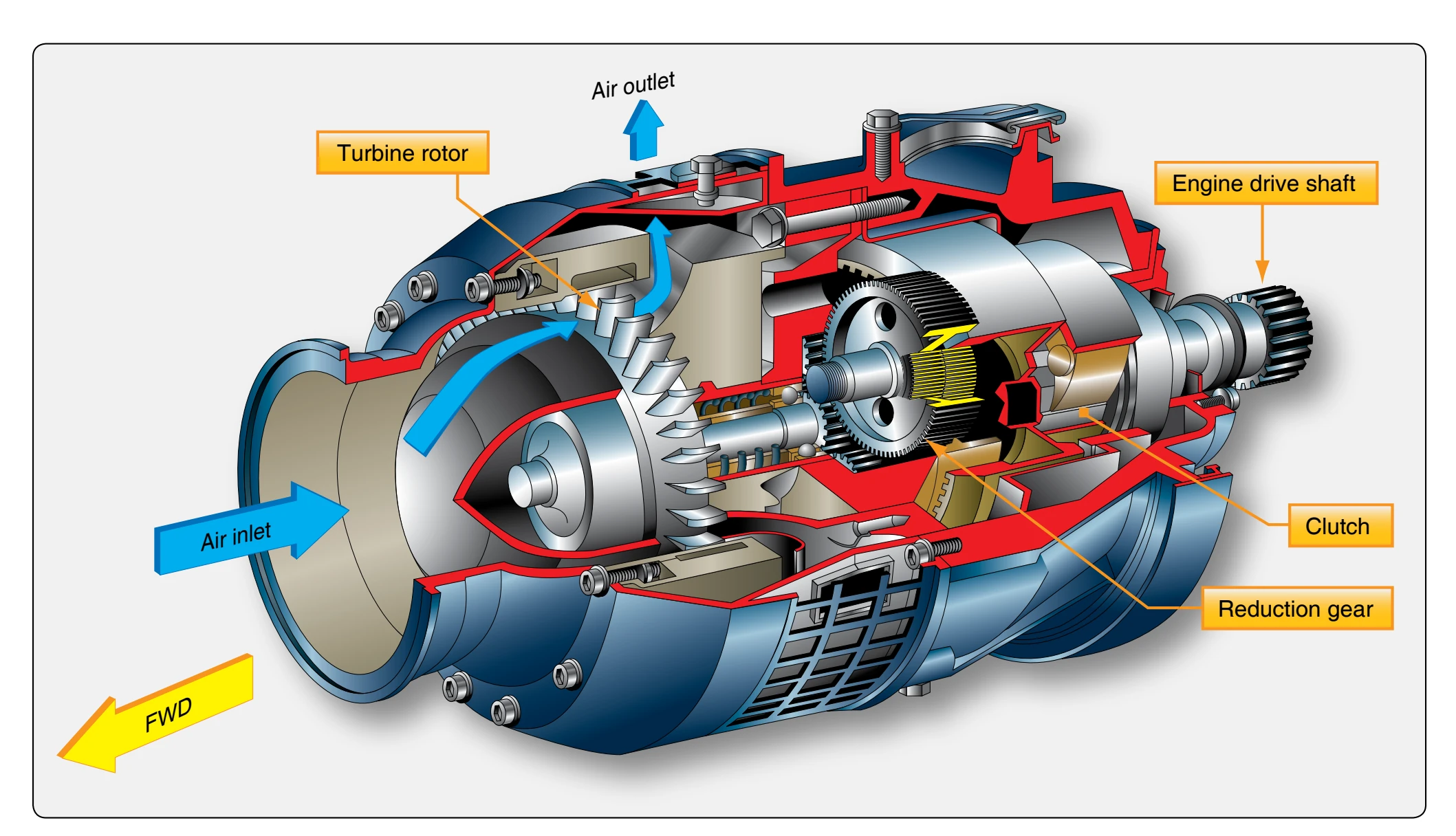
Figure 5-21 is a cutaway view of an air turbine starter. The starter is operated by introducing air of sufficient volume and pressure into the starter inlet. The air passes into the starter turbine housing where it is directed against the rotor blades by the nozzle vanes causing the turbine rotor to turn. As the rotor turns, it drives the reduction gear train and clutch arrangement, which includes the rotor pinion, planet gears and carrier, sprag clutch assembly, output shaft assembly, and drive coupling. The sprag clutch assembly engages automatically as soon as the rotor starts to turn but disengages as soon as the drive coupling turns more rapidly than the rotor side. When the starter reaches this overrun speed, the action of the sprag clutch allows the gear train to coast to a halt. The output shaft assembly and drive coupling continue to turn as long as the engine is running. A rotor switch actuator, mounted in the turbine rotor hub, is set to open the turbine switch when
the starter reaches cutout speed. Opening the turbine switch interrupts an electrical signal to the start valve. This closes the valve and shuts off the air supply to the starter.
The turbine housing contains the turbine rotor, the rotor switch actuator, and the nozzle components that direct the inlet air against the rotor blades. The turbine housing incorporates a turbine rotor containment ring designed to dissipate the energy of blade fragments and direct their discharge at low energy through the exhaust duct in the event of rotor failure due to excessive turbine overspeed.
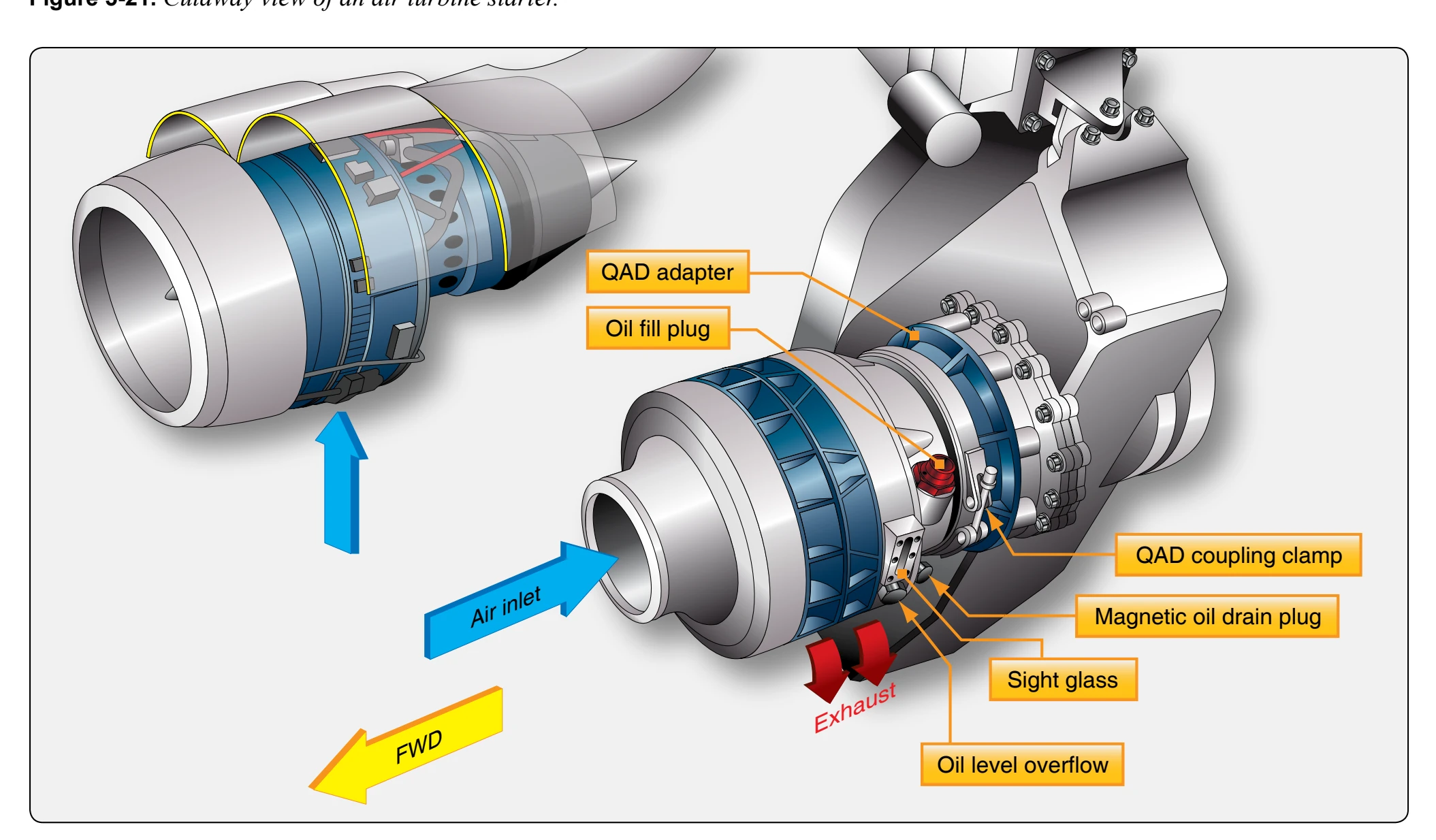
The transmission housing contains the reduction gears, the clutch components, and the drive coupling. The transmission housing also provides a reservoir for the lubricating oil. [Figure 5-22] Normal maintenance for air turbine starters includes checking the oil level, inspecting the magnetic chip detector for metal particles, and checking for leaks. Oil can be added to the transmission housing sump through a port in the starter. This port is closed by a vent plug containing a ball valve that allows the sump to be vented to the atmosphere during normal flight. The housing also incorporates a sight gauge that is used to check the oil quantity. A magnetic drain plug in the transmission drain opening attracts any ferrous particles that may be in the oil. The starter uses turbine oil, the same as the engine, but this oil does not circulate through the engine.
The ring gear housing, which is internal, contains the rotor assembly. The switch housing contains the turbine switch and bracket assembly. To facilitate starter installation and removal, a mounting adapter is bolted to the mounting pad on the engine. Quick-detach clamps join the starter to the mounting adapter and inlet duct. [Figure 5-22] Thus, the starter is easily removed for maintenance or overhaul by disconnecting the electrical line, loosening the clamps, and carefully disengaging the drive coupling from the engine starter drive as the starter is withdrawn.
The air path is directed through a combination pressureregulating and shutoff valve, or bleed valve, that controls all duct pressure flowing to the starter inlet ducting. This valve regulates the pressure of the starter operating air and shuts off the air supply to the engine when selected off. Downstream from the bleed valve is the start valve, which is used to control air flow into the starter. [Figure 5-23]
The pressure-regulating and shutoff valve consists of two subassemblies: pressure-regulating valve and pressure-
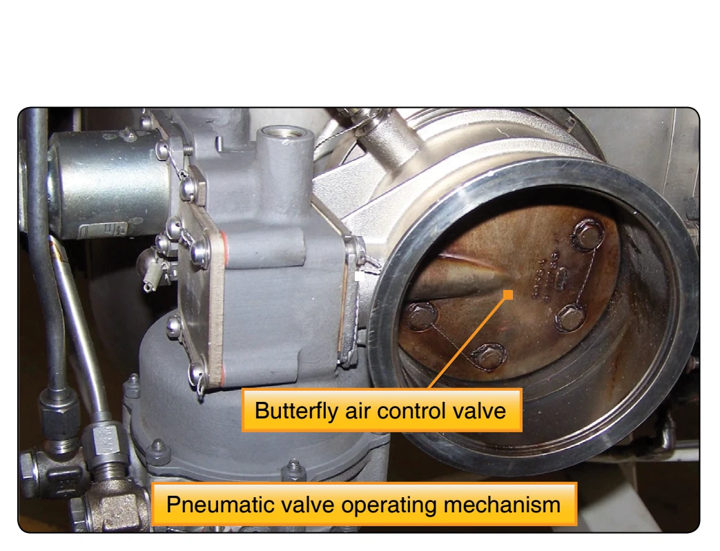
regulating valve control. [Figure 5-24] The regulating valve assembly consists of a valve housing containing a butterflytype valve. [Figure 5-24] The shaft of the butterfly valve is connected through a cam arrangement to a servo piston. When the piston is actuated, its motion on the cam causes rotation of the butterfly valve. The slope of the cam track is designed to provide small initial travel and high initial torque when the starter is actuated. The cam track slope also provides more stable action by increasing the opening time of the valve.
The control assembly is mounted on the regulating valve housing and consists of a control housing in which a solenoid is used to stop the action of the control crank in the off position. [Figure 5-24] The control crank links a pilot valve that meters pressure to the servo piston, with the bellows connected by an air line to the pressure-sensing port on the starter.