
Chapter 5
Engine Starting Systems
are automatically cut off. The basic types of starters that are in current use for gas turbine engines are direct current (DC) electric motor, starter/generators, and the air turbine type of starters.
Many types of turbine starters have included several different methods for turning the engine for starting. Several methods have been used but most of these have given way to electric or air turbine starters. An air impingement starting system, which is sometimes used on small engines, consists of jets of compressed air piped to the inside of the compressor or turbine case so that the jet air blast is directed onto the compressor or turbine rotor blades, causing them to rotate.
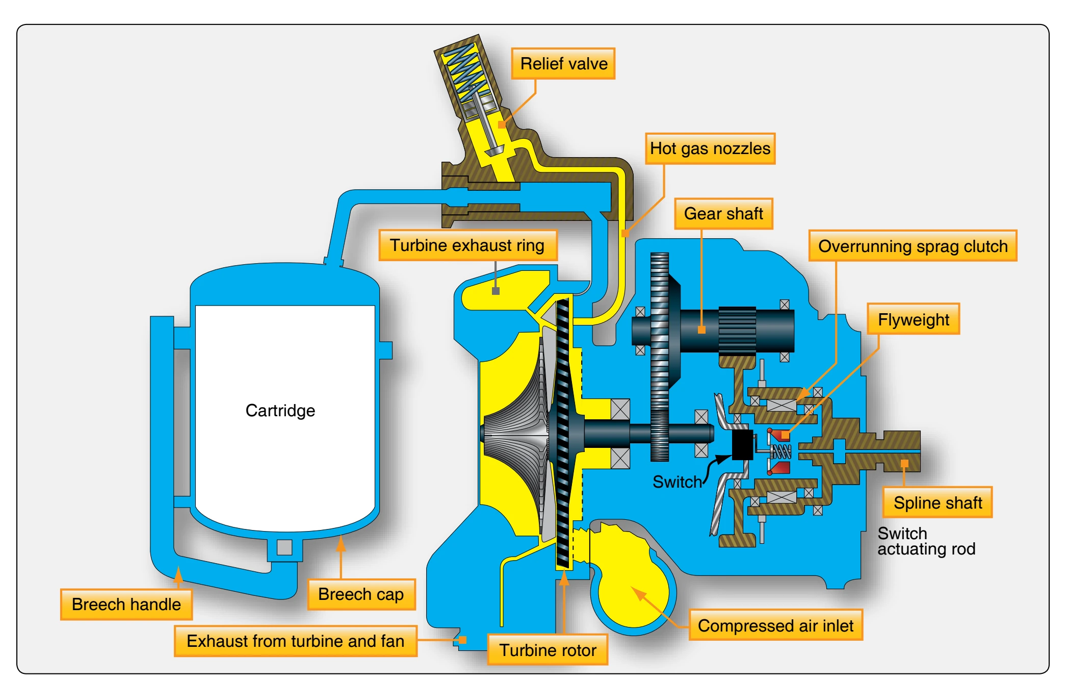
A typical cartridge/pneumatic turbine engine starter may be operated as an ordinary air turbine starter from a groundoperated air supply or an engine cross-bleed source. It may also be operated as a cartridge starter. [Figure 5-15] To accomplish a cartridge start, a cartridge is first placed in the breech cap. The breech is then closed on the breech chamber by means of the breech handle and then rotated a partial turn to engage the lugs between the two breech sections. The cartridge is ignited by applying voltage through the connector at the end of the breech handle. Upon ignition, the cartridge begins to generate gas. The gas is forced out of the breech to the hot gas nozzles that are directed toward the buckets on the turbine rotor, and rotation is produced via the overboard exhaust collector. Before reaching the nozzle, the hot gas passes an outlet leading to the relief valve. This valve directs hot gas to the turbine, bypassing the hot gas nozzle, as the pressure rises above the preset maximum. Thus, the pressure of the gas within the hot gas circuit is maintained at the optimum level.
The air-fuel combustion starter was used to start gas turbine
engines by using the combustion energy of jet A fuel and compressed air. The starter consists of a turbine-driven power unit and auxiliary fuel, air, and ignition systems. Operation of this type starter is, in most installations, fully automatic; actuation of a single switch causes the starter to fire and accelerate the engine from rest to starter cutoff speed.
Hydraulic pumps and motors have also been used for some smaller engines. Many of these systems are not often used on modern commercial aircraft because of the high power demands required to turn the large turbofan engines during the starting cycle on transport aircraft.
Electric Starting Systems & Starter Generator Starting System
Electric starting systems for gas turbine aircraft are of two general types: direct cranking electrical systems and starter generator systems. Direct cranking electric starting systems are used mostly on small turbine engines, such as Auxiliary Power Units (APUs), and some small turboshaft engines. Many gas turbine aircraft are equipped with starter generator systems. Starter generator starting systems are also similar to direct cranking electrical systems except that after functioning as a starter, they contain a second series of windings that allow it to switch to a generator after the engine has reached a self-sustaining speed. This saves weight and space on the engine.
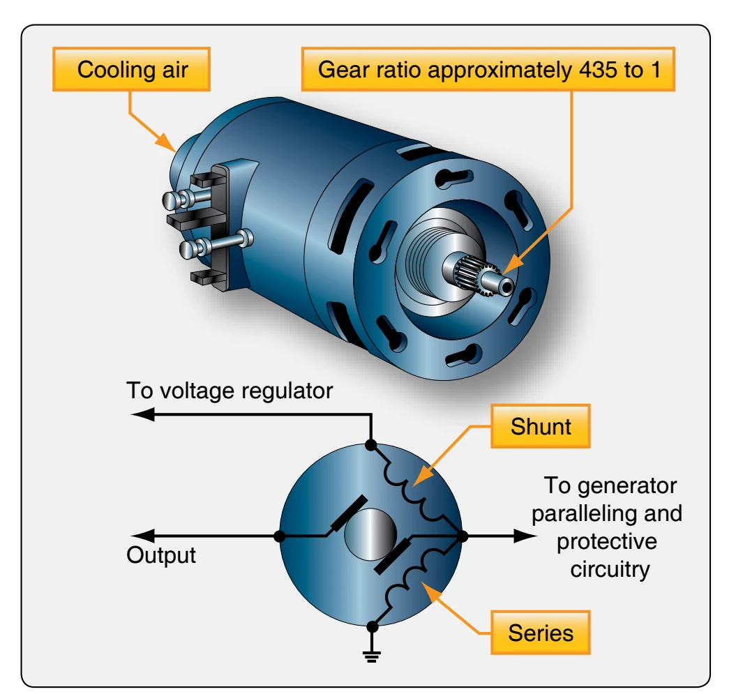
The starter generator is permanently engaged with the engine shaft through the necessary drive gears, while the direct cranking starter must employ some means of disengaging the starter from the shaft after the engine has started. The starter generator unit is basically a shunt generator with an additional heavy series winding. [Figure 5-16] This series winding is electrically connected to produce a strong field and a resulting high torque for starting. Starter generator units are desirable from an economic standpoint, since one unit performs the functions of both starter and generator. Additionally, the total weight of starting system components is reduced and fewer spare parts are required.
The starter generator internal circuit has four field windings: a series field (C field), a shunt field, a compensating field, and an interpole or commutating winding. [Figure 5-17] During starting, the C field, compensating, and commutating windings are used. The unit is similar to a direct cranking starter since all of the windings used during starting are in series with the source. While acting as a starter, the unit makes no practical use of its shunt field. A source of 24 volts and 1,500 peak amperes is usually required for starting.
When operating as a generator, the shunt, compensating, and commutating windings are used. The C field is used
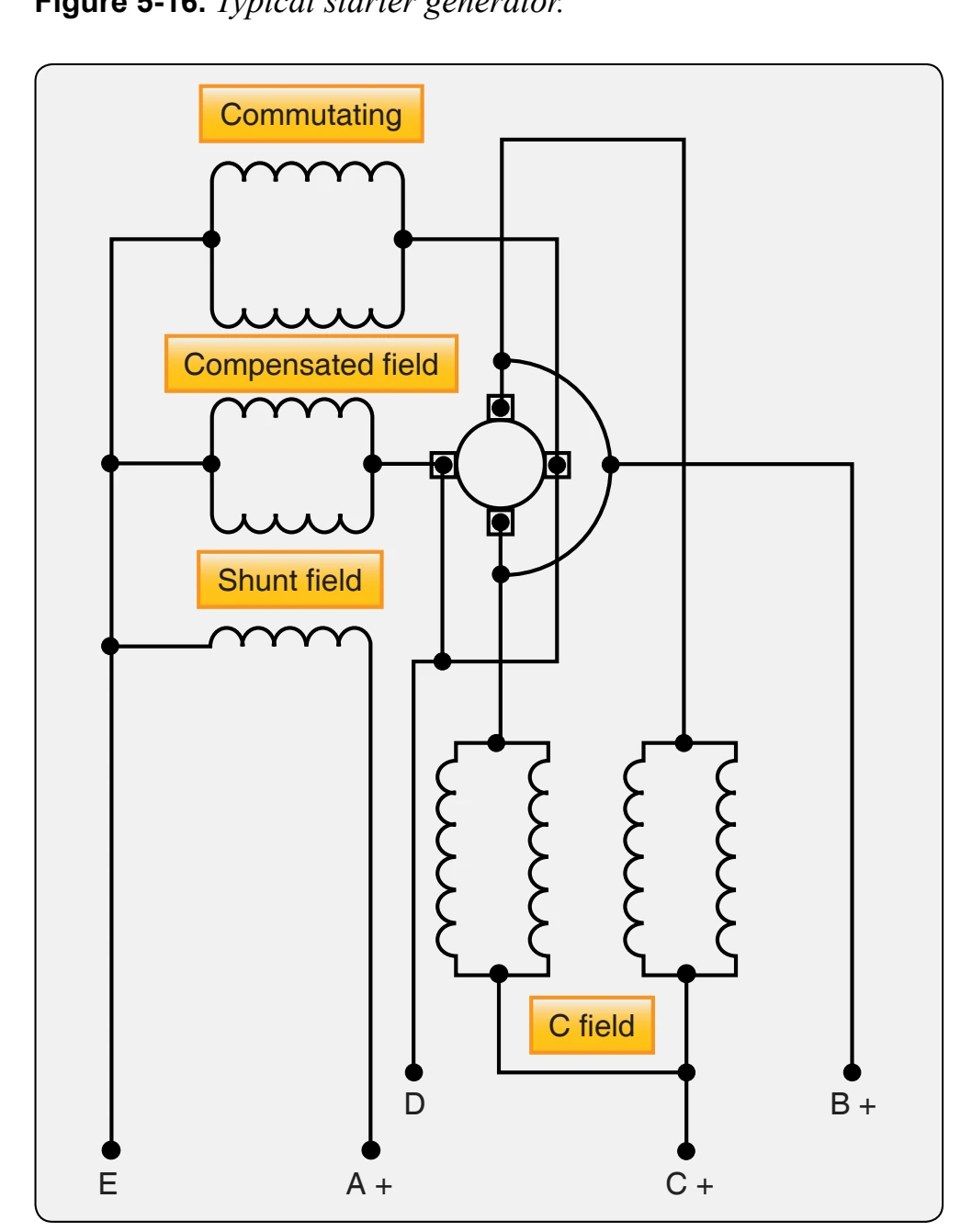
only for starting purposes. The shunt field is connected in the conventional voltage control circuit for the generator. Compensating and commutating or interpole windings provide almost sparkless commutation from no load to full load. Figure 5-18 illustrates the external circuit of a starter generator with an undercurrent controller. This unit controls the starter generator when it is used as a starter. Its purpose is
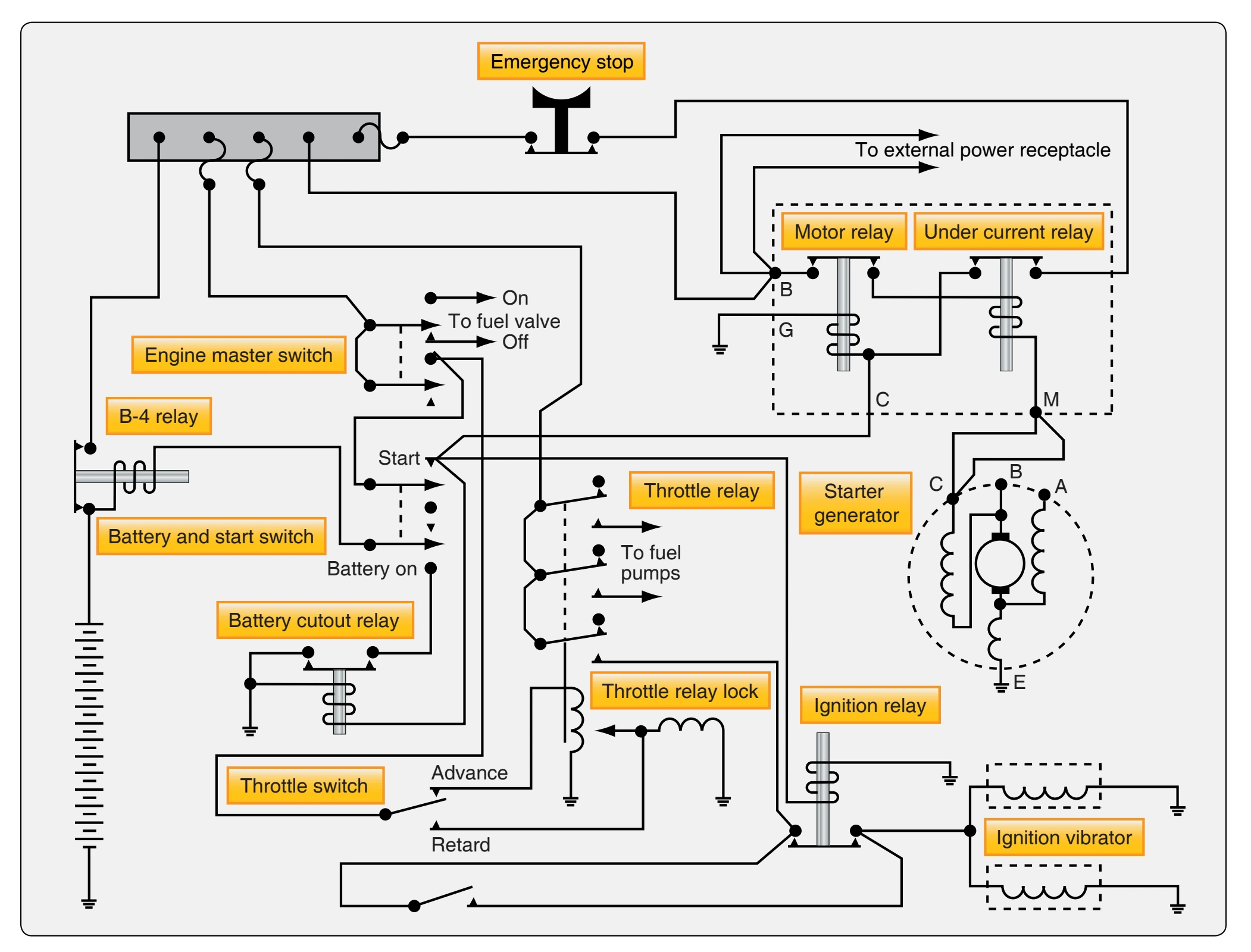
to assure positive action of the starter and to keep it operating until the engine is rotating fast enough to sustain combustion. The control block of the undercurrent controller contains two relays. One is the motor relay that controls the input to the starter; the other, the undercurrent relay, controls the operation of the motor relay.
The sequence of operation for the starting system is discussed in the following paragraphs. [Figure 5-18] To start an engine equipped with an undercurrent relay, it is first necessary to close the engine master switch. This completes the circuit from the aircraft’s bus to the start switch, to the fuel valves, and to the throttle relay. Energizing the throttle relay starts the fuel pumps and completing the fuel valve circuit gives the necessary fuel pressure for starting the engine. As the battery and start switch is turned on, three relays close: the motor relay, ignition relay, and battery cutout relay. The motor relay closes the circuit from the power source to the starter motor; the ignition relay closes the circuit to the ignition units; the battery cutout relay disconnects the battery. Opening the battery circuit is necessary because the heavy drain of the starter motor would damage the battery. Closing the motor relay allows a very high current to flow to the motor. Since this current flows through the coil of the undercurrent relay, it closes. Closing the undercurrent relay completes a circuit from the positive bus to the motor relay coil, ignition relay coil, and battery cutout relay coil. The start switch is allowed to return to its normal off position, and all units continue to operate.
As the motor builds up speed, the current draw of the motor begins to decrease. As it decreases to less than 200 amps, the undercurrent relay opens. This action breaks the circuit from the positive bus to the coils of the motor, ignition, and battery cutout relays. The de-energizing of these relay coils halts the start operation.
After these procedures are completed, the engine should be operating efficiently, and ignition should be self-sustaining. If, however, the engine fails to reach sufficient speed to halt the starter operation, the stop switch may be used to break the circuit from the positive bus to the main contacts of the undercurrent relay.