
Chapter 6
Lubrication & Cooling Systems
An air seal is constructed of rubber material, bolted to a metal rib riveted to the cowl panel. [Figure 6-55] This seal, as the name implies, seals the air in the engine section, preventing the air from escaping along the inner surface of the panel without circulating around the cylinders. The engine air seal must be used on engines that have a complete cylinder baffling system that covers the cylinder heads. Its purpose is to force the air to circulate around and through the baffle system. Inspect the cowl panels during each regular engine and aircraft inspection. Removing the cowling for maintenance provides an opportunity for a more detailed inspection of the cowling.
Inspect the cowling panels for scratches, dents, and tears in the panels. This type of damage causes weakness of the panel structure, increases drag by disrupting airflow, and contributes to the starting of corrosion. The cowling panel latches should be inspected for pulled rivets and loose or damaged handles. The internal construction of the panel should be examined to see that the reinforcing ribs are not cracked and that the air seal is not damaged. The cowl flap hinges, if equipped, and cowl flap hinge bondings should be checked for security of mounting and for breaks or cracks. These inspections are visual checks and should be performed frequently to ensure that the cowling is serviceable and is contributing to efficient engine cooling.
Engine Cylinder Cooling Fin Inspection
The cooling fins are of the utmost importance to the cooling system, since they provide a means of transferring the cylinder heat to the air. Their condition can mean the difference between adequate or inadequate cylinder cooling. The fins are inspected at each regular inspection. Fin area is the total area (both sides of the fin) exposed to the air. During the inspection, the fins should be examined for cracks and breaks. [Figure 6-56] Small cracks are not a
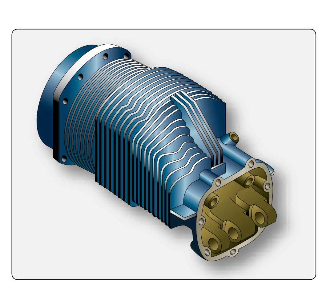
reason for cylinder removal. These cracks can be filled or even sometimes stop-drilled to prevent any further cracking. Rough or sharp corners on fins can be smoothed out by filing, and this action eliminates a possible source of new cracks. However, before reprofiling cylinder cooling fins, consult the manufacturer’s service or overhaul manual for the allowable limits.
The definition of fin area becomes important in the examination of fins for broken areas. It is a determining factor for cylinder acceptance or removal. For example, on a certain engine, if more than 12 inches in length of any one fin, as measured at its base, is completely broken off, or if the total fins broken on any one cylinder head exceed 83 square inches of area, the cylinder is removed and replaced. The reason for removal in this case is that an area of that size would cause a hot spot on the cylinder; since very little heat transfer could occur.
Where adjacent fins are broken in the same area, the total length of breakage permissible is six inches on any two adjacent fins, four inches on any three adjacent fins, two inches on any four adjacent fins, and one inch on any five adjacent fins. If the breakage length in adjacent fins exceeds this prescribed amount, the cylinder should be removed and replaced. These breakage specifications are applicable only to the engine used in this discussion as a typical example. In each specific case, applicable manufacturer’s instructions should be consulted.
Cylinder Baffle & Deflector System Inspection
Reciprocating engines use some type of intercylinder and cylinder head baffles to force the cooling air into close contact with all parts of the cylinders. Figure 6-50 shows a baffle and deflector system around a cylinder. The air baffle
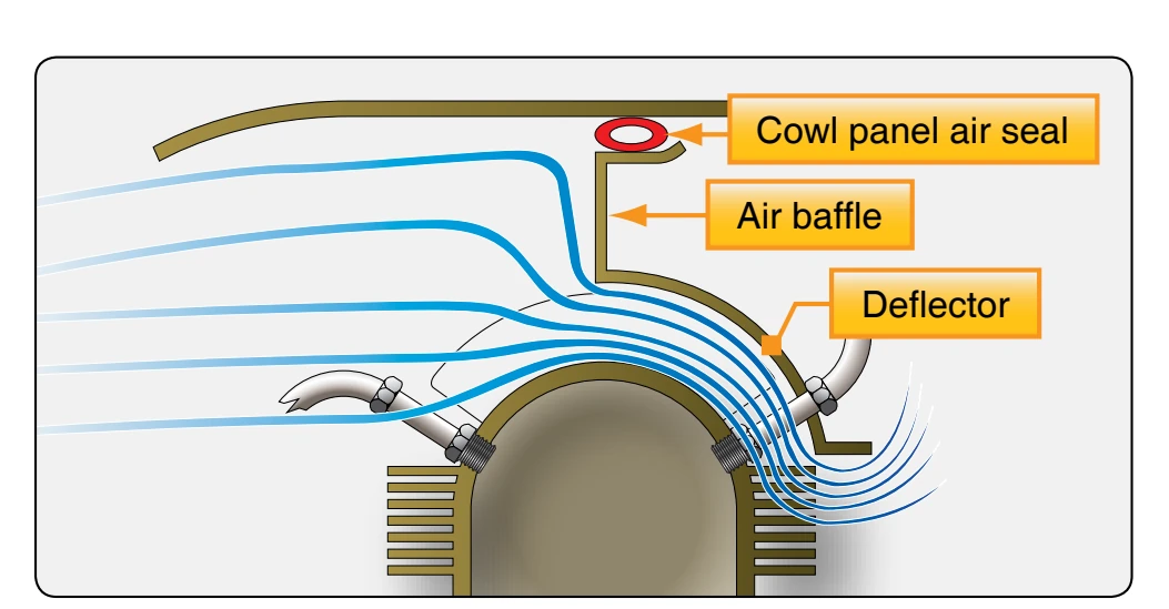
blocks the flow of air and forces it to circulate between the cylinder and the deflectors. Figure 6-57 illustrates a baffle and deflector arrangement designed to cool the cylinder head. The air baffle prevents the air from passing away from the cylinder head and forces it to go between the head and deflector. Although the resistance offered by baffles to the passage of the cooling air demands that an appreciable pressure differential be maintained across the engine to obtain the necessary airflow, the volume of cooling air required is greatly reduced by employing properly designed and located cylinder deflectors.
As shown in Figure 6-55, the airflow approaches the nacelle and piles up at the top of the engine, creating a high pressure in the top of the cylinders. This piling up of the air reduces the air velocity. The outlet at the bottom rear of the cowling produces a low-pressure area. As the air nears the cowl exit, it is speeded up again and merges smoothly with the airstream. The pressure differential between the top and the bottom of the engine forces the air past the cylinders through the passages formed by the deflectors. The baffles and deflectors normally are inspected during the regular engine inspection, but they should be checked whenever the cowling is removed for any purpose. Checks should be made for cracks, dents, or loose hold down studs. Cracks or dents, if severe enough, would necessitate repair or removal and replacement of these units. However, a crack that has just started can be stop-drilled, and dents can be straightened, permitting further service from these baffles and deflectors.
Cylinder Temperature Indicating Systems
This system usually consists of an indicator, electrical wiring, and a thermocouple. The wiring is between the instrument and the nacelle firewall. At the firewall, one end of the thermocouple leads connects to the electrical wiring, and the other end of the thermocouple leads connects to the cylinder. The thermocouple consists of two dissimilar metals, generally constantan and iron, connected by wiring to an indicating system. If the temperature of the junction is different from the temperature where the dissimilar metals are connected to wires, a voltage is produced. This voltage sends a current through wires to the indicator, a current-measuring instrument
graduated in degrees.
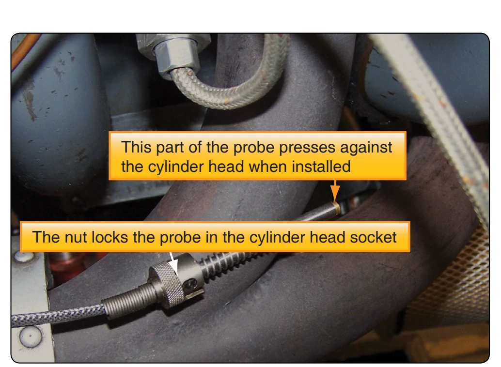
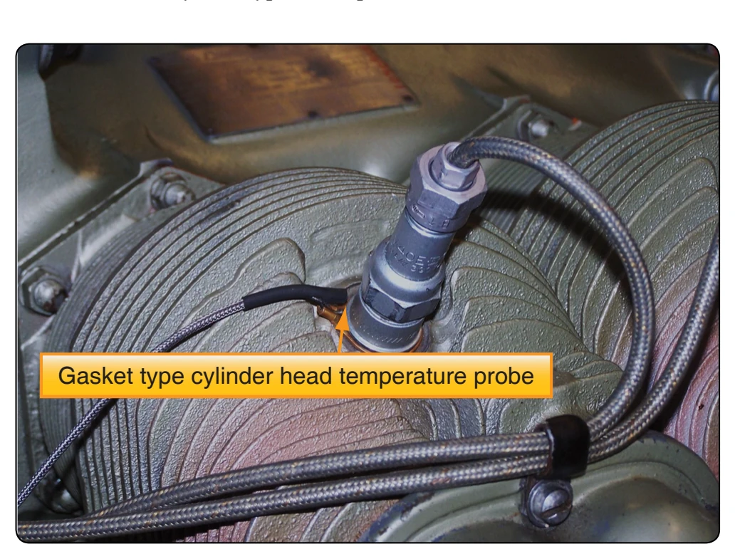
The thermocouple end that connects to the cylinder is either the bayonet or gasket type. To install the bayonet type, the knurled nut is pushed down and turned clockwise until it is snug. [Figure 6-58] In removing this type, the nut is pushed down and turned counterclockwise until released. The gasket type fits under the spark plug and replaces the normal spark plug gasket. [Figure 6-59] When installing a thermocouple lead, remember not to cut off the lead because it is too long, but coil and tie up the excess length. The thermocouple is designed to produce a given amount of resistance. If the length of the lead is reduced, an incorrect temperature reading results. The bayonet or gasket of the thermocouple is inserted or installed on the hottest cylinder of the engine, as determined in the block test. When the thermocouple is installed and the wiring connected to the instrument, the indicated reading is the cylinder temperature. Prior to operating the engine, provided it is at ambient temperature, the cylinder head temperature indicator indicates the free outside air temperature; that is one test for determining that the instrument is working correctly. The cover glass of the cylinder head temperature indicator should be checked regularly to see that it has not slipped or cracked. The cover glass should be checked for indications of missing or damaged decals that indicate temperature limitations. If the thermocouple leads were excessive in length and had to be coiled and tied down, the tie should be inspected for security or chafing of the wire. The bayonet or gasket should be inspected for cleanness and security of mounting. When operating the engine, all of the electrical connections should be checked if the cylinder head temperature pointer fluctuates.