
Chapter 6
Lubrication & Cooling Systems
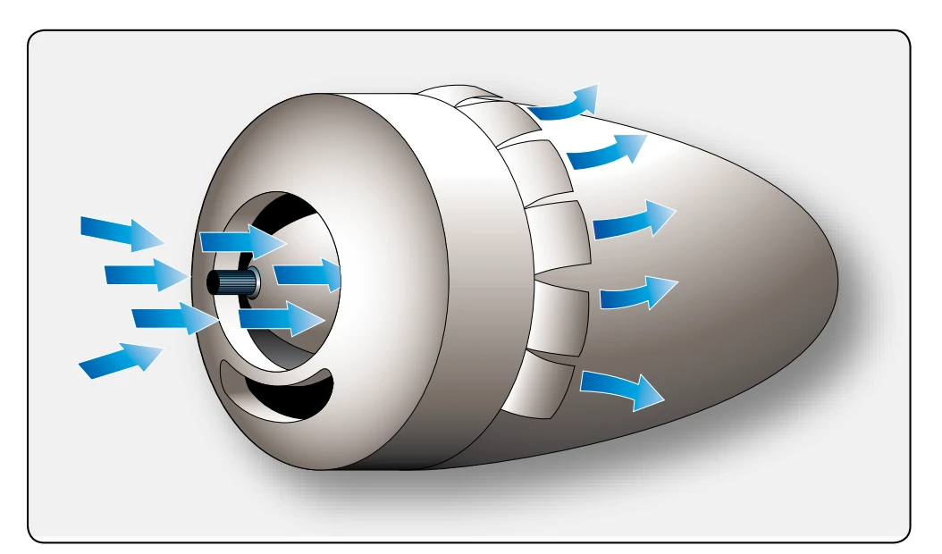
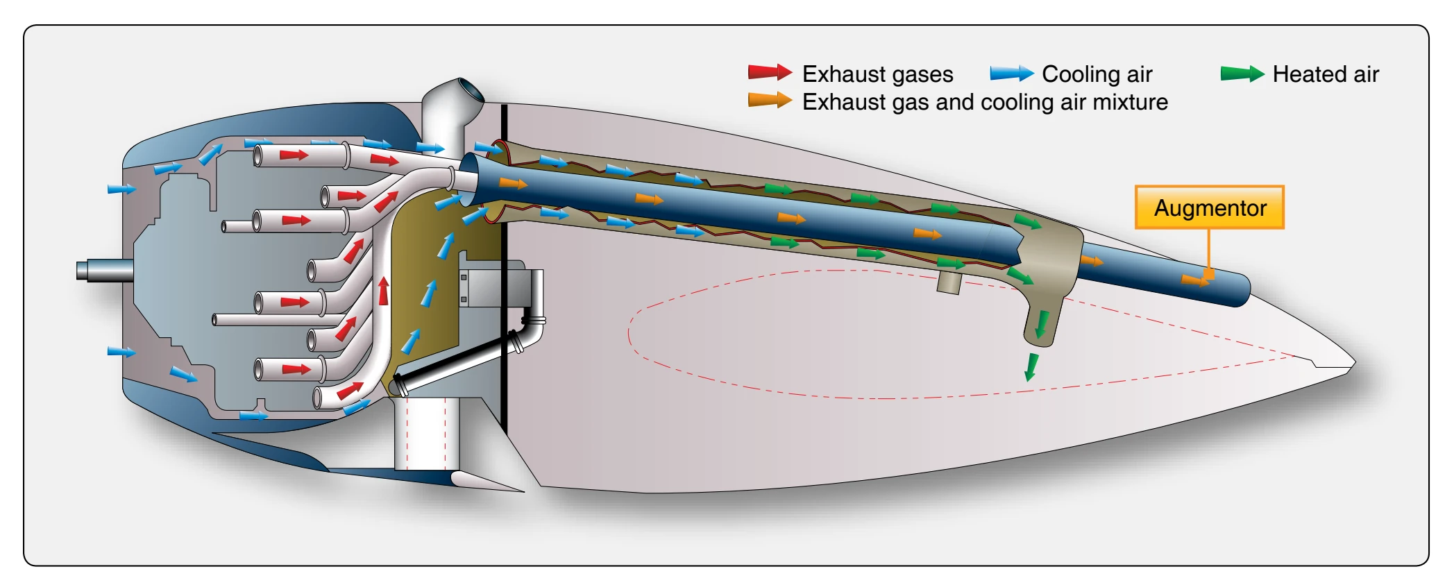
Some aircraft use augmentors to provide additional cooling airflow. [Figure 6-52] Each nacelle has two pairs of tubes running from the engine compartment to the rear of the nacelle. The exhaust collectors feed exhaust gas into the inner augmentor tubes. The exhaust gas mixes with air that has passed over the engine and heats it to form a high-temperature, low-pressure, jet-like exhaust. This low-pressure area in the augmentors draws additional cooling air over the engine. Air entering the outer shells of the augmentors is heated through contact with the augmentor tubes but is not contaminated with exhaust gases. The heated air from the shell goes to the cabin heating, defrosting, and anti-icing system.
Augmentors use exhaust gas velocity to cause airflow over the engine so that cooling is not entirely dependent on the prop wash. Vanes installed in the augmentors control the volume of air. These vanes are usually left in the trail position to permit maximum flow. They can be closed to increase the heat for cabin or anti-icing use or to prevent the engine from cooling too much during descent from altitude. In addition to augmentors, some aircraft have residual heat doors or nacelle flaps that are used mainly to let the retained heat escape after engine shutdown. The nacelle flaps can be opened for more cooling than that provided by the augmentors. A modified form of the previously described augmentor cooling system is used on some light aircraft. [Figure 6-53] Augmentor systems are not used much on modern aircraft.
As shown in Figure 6-53, the engine is pressure cooled by air taken in through two openings in the nose cowling, one on each side of the propeller spinner. A pressure chamber is sealed off on the top side of the engine with baffles properly directing the flow of cooling air to all parts of the engine compartment. Warm air is drawn from the lower part of the engine compartment by the pumping action of the exhaust
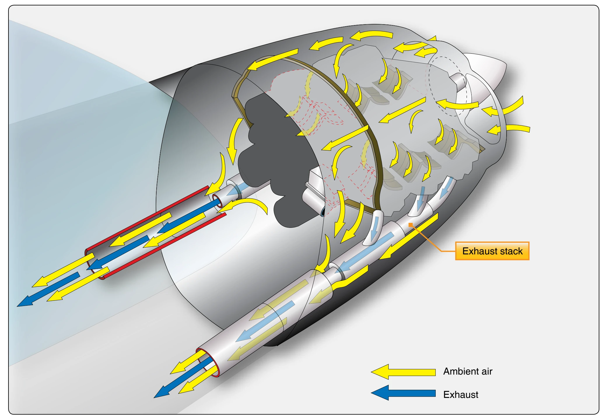
gases through the exhaust ejectors. This type of cooling system eliminates the use of controllable cowl flaps and assures adequate engine cooling at all operating speeds.
Reciprocating Engine Cooling System Maintenance
The engine cooling system of most reciprocating engines usually consists of the engine cowling, cylinder baffles, cylinder fins, and some use a type of cowl flaps. In addition to these major units, there are also some temperature-indicating systems, such as cylinder head temperature, oil temperature, and exhaust gas temperature.
The cowling performs two functions:
- It streamlines the bulky engine to reduce drag.
- It forms an envelope around the engine that forces air to pass around and between the cylinders, absorbing the heat dissipated by the cylinder fins.
The cylinder bases are metal shields, designed and arranged to direct the flow of air evenly around all cylinders. This even distribution of air aids in preventing one or more cylinders from being excessively hotter than the others. The cylinder fins radiate heat from the cylinder walls and heads. As the air passes over the fins, it absorbs this heat, carries it away from the cylinder, and is exhausted overboard through the bottom rear of the cowl.
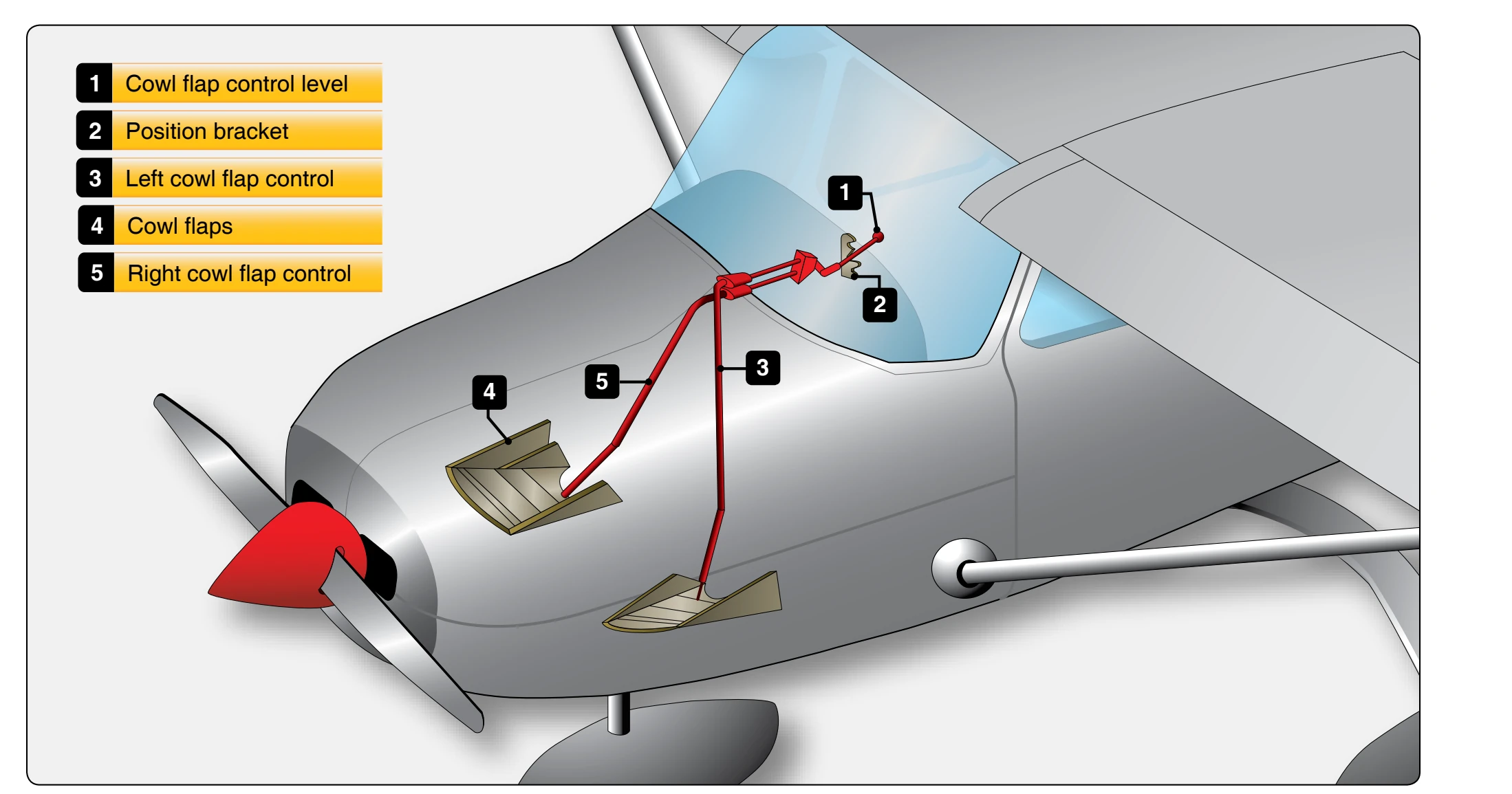
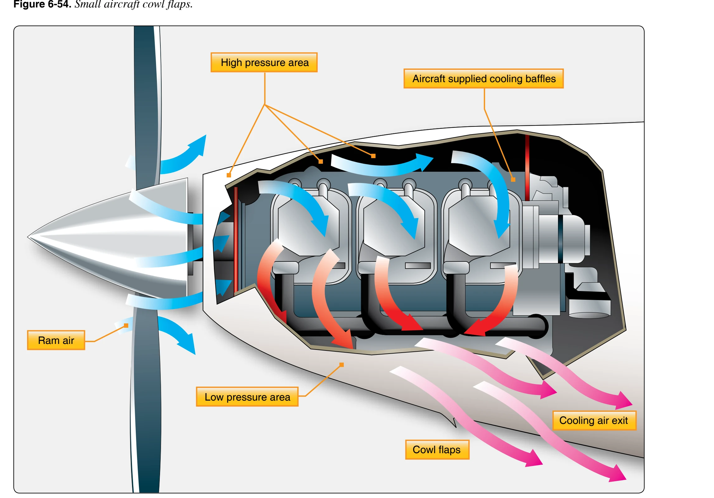
The controllable cowl flaps provide a means of decreasing or increasing the exit area at the rear of the engine cowling. [Figure 6-54] Closing the cowl flaps decreases the exit area, which effectively decreases the amount of air that can circulate over the cylinder fins. The decreased airflow cannot carry away as much heat; therefore, it has a tendency for the engine temperature to increase. Opening the cowl flaps makes the exit area larger. The flow of cooling air over the cylinders increases, absorbing more heat and the engine temperature tends to decrease. Good inspection and maintenance in the care of the engine cooling system aids in overall efficient and economical engine operation.
Maintenance of Engine Cowling
Of the total ram airflow approaching the airborne engine nacelle, only about 15 to 30 percent enters the cowling to provide engine cooling. The remaining air flows over the outside of the cowling. Therefore, the external shape of the cowl must be faired in a manner that permits the air to flow smoothly over the cowl with a minimum loss of energy.
The engine cowling discussed in this section is typical of that used on many radial or horizontally opposed engines. All cooling systems function in the same manner, with minor engineering changes designed for specific installations.
The cowl is manufactured in removable sections, the number varies with the aircraft make and model. The installation shown in Figure 6-55 contains two sections that are locked together when installed.
The cowl panels, made from sheet aluminum or composite material, have a smooth external surface to permit undisturbed airflow over the cowl. The internal construction is designed to give strength to the panel and, in addition, to provide receptacles for the toggle latches, cowl support, and engine air seal.