Chapter 6
Lubrication & Cooling Systems
through drilled passages to the crankshaft bearings and other bearings throughout the engine. Oil flows from the main bearings through holes drilled in the crankshaft to the lower connecting rod bearings. [Figure 6-15]
Oil reaches a hollow camshaft (in an inline or opposed engine), or a cam plate or cam drum (in a radial engine), through a connection with the end bearing or the main oil manifold; it then flows out to the various camshaft, cam drum, or cam plate bearings and the cams.
The engine cylinder surfaces receive oil sprayed from the crankshaft and also from the crankpin bearings. Since oil seeps slowly through the small crankpin clearances before it is sprayed on the cylinder walls, considerable time is required for enough oil to reach the cylinder walls, especially on a cold day when the oil flow is more sluggish. This is one of the chief reasons for using modern multiviscosity oils that flow well at low temperatures.
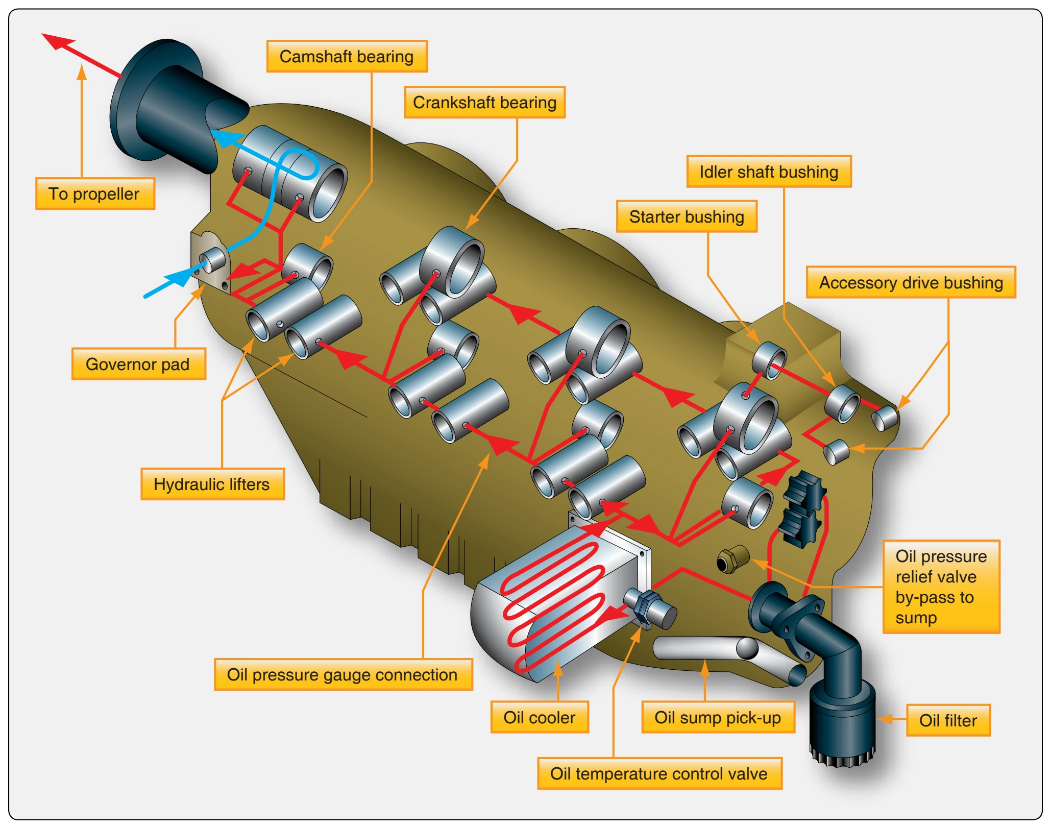
When the circulating oil has performed its function of lubricating and cooling the moving parts of the engine, it drains into the sumps in the lowest parts of the engine. Oil collected in these sumps is picked up by gear or gerotor-type scavenger pumps as quickly as it accumulates. These pumps have a greater capacity than the pressure pump. This is needed because the volume of the oil has generally increased due to foaming (mixing with air). On dry sump engines, this oil leaves the engine, passes through the oil cooler, and returns to the supply tank.
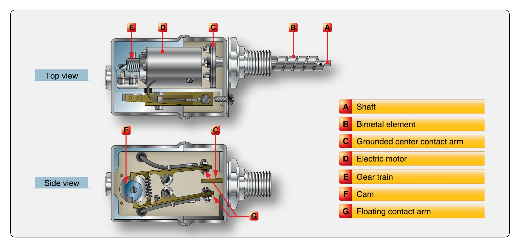
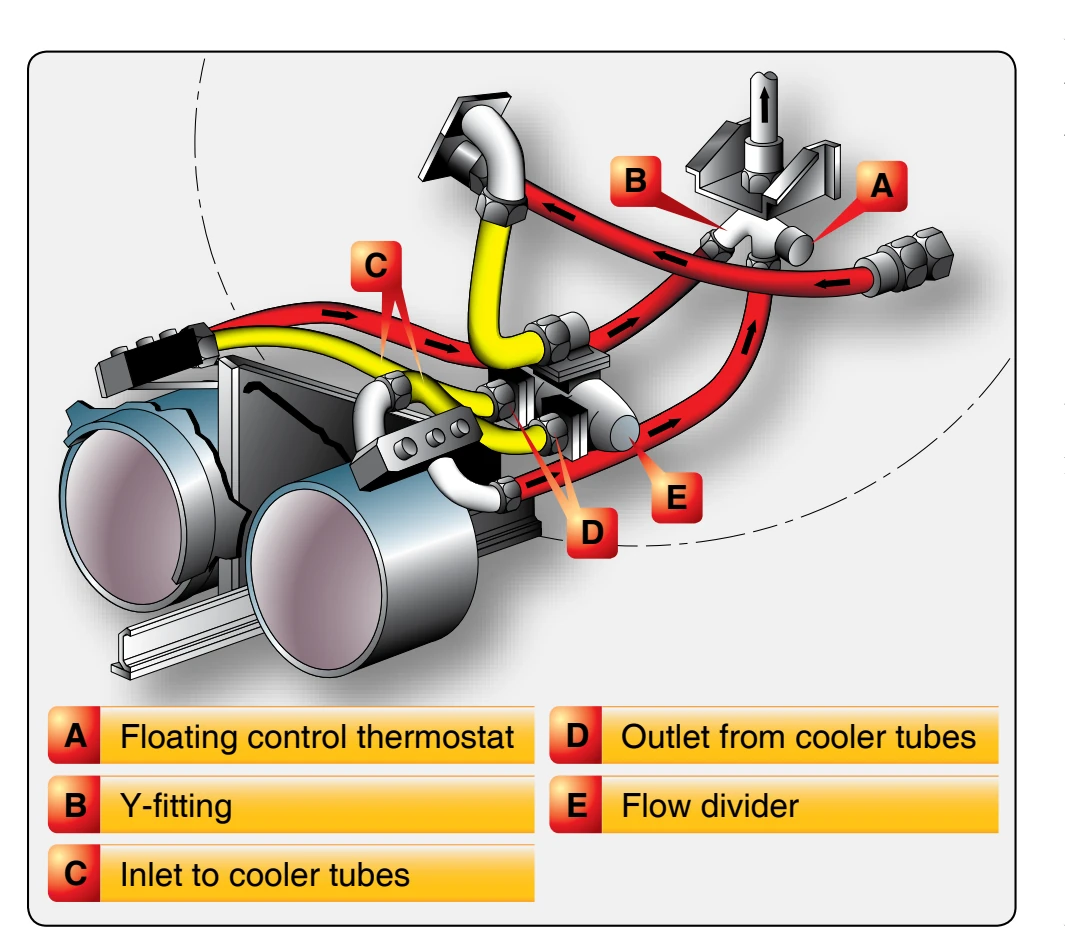
A thermostat attached to the oil cooler controls oil temperature by allowing part of the oil to flow through the cooler and part to flow directly into the oil supply tank. This arrangement allows hot engine oil with a temperature still below 65 °C (150 °F) to mix with the cold uncirculated oil in the tank. This raises the complete engine oil supply to operating temperature in a shorter period of time.
Wet-Sump Lubrication System Operation
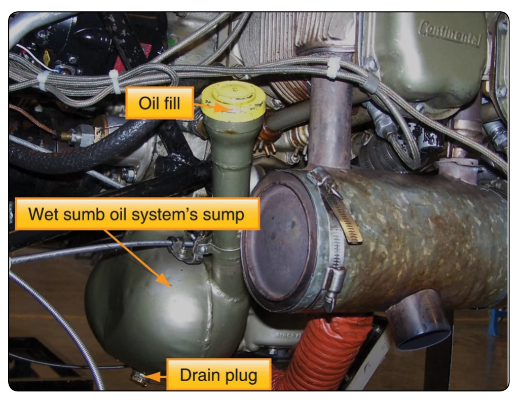
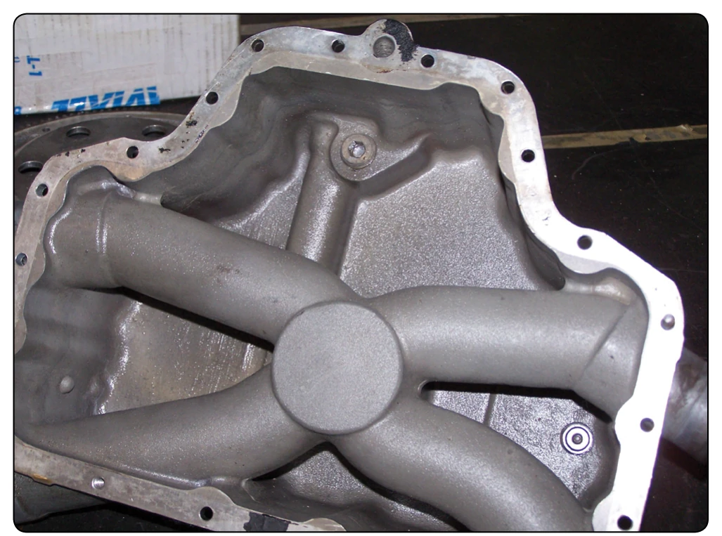
A simple form of a wet-sump system is shown in Figure 6-16. The system consists of a sump or pan in which the oil supply is contained. The oil supply is limited by the sump (oil pan) capacity. The level (quantity) of oil is indicated or measured by a vertical rod that protrudes into the oil from an elevated hole on top of the crankcase. In the bottom of the sump (oil pan) is a screen strainer having a suitable mesh, or series of openings, to strain undesirable particles from the oil and yet pass sufficient quantity to the inlet or (suction) side of the oil pressure pump. Figure 6-17 shows a typical oil sump that has the intake tube running through it. This preheats the air-fuel mixture before it enters the cylinders.
The rotation of the pump, which is driven by the engine, causes the oil to pass around the outside of the gears. [Figure 6-6] This develops a pressure in the crankshaft oiling system (drilled passage holes). The variation in the
speed of the pump from idling to full-throttle operating range of the engine and the fluctuation of oil viscosity because of temperature changes are compensated by the tension on the relief valve spring. The pump is designed to create a greater pressure than required to compensate for wear of the bearings or thinning out of oil. The parts oiled by pressure throw a lubricating spray into the cylinder and piston assemblies. After lubricating the various units it sprays, the oil drains back into the sump and the cycle is repeated. The system is not readily adaptable to inverted flying since the entire oil supply floods the engine.
Lubrication System Maintenance Practices
Oil Tank
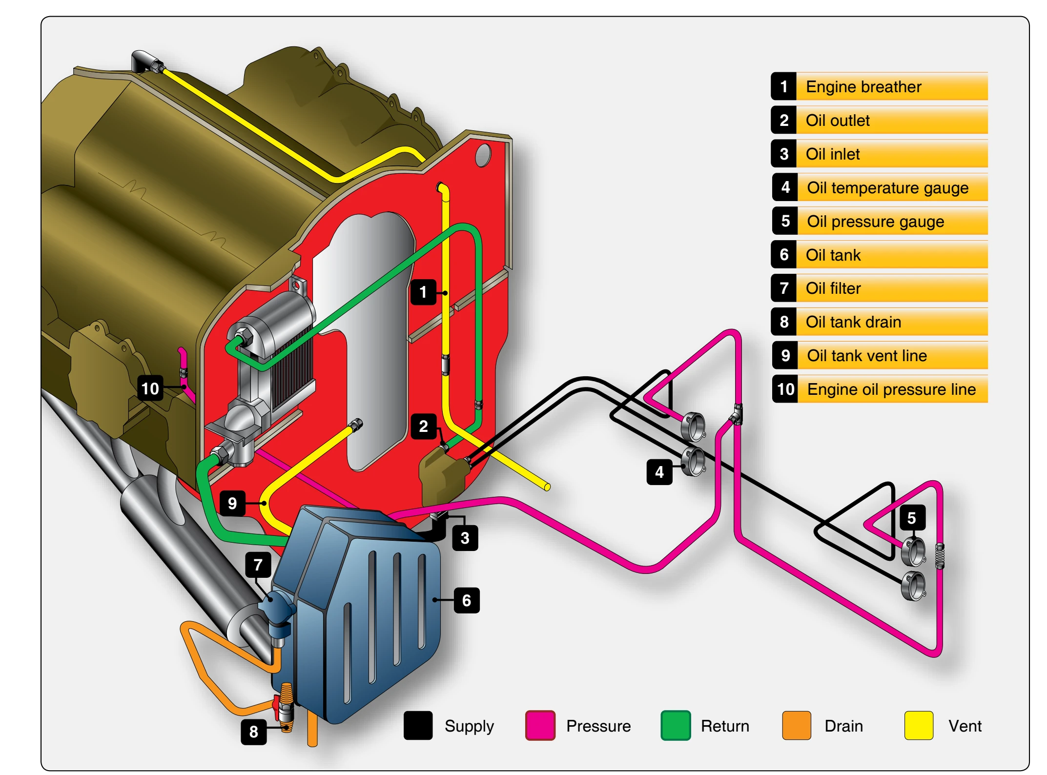
The oil tank, constructed of welded aluminum, is serviced (filled) through a filler neck located on the tank and equipped with a spring-loaded locking cap. Inside the tank, a weighted, flexible rubber oil hose is mounted so that it is repositioned automatically to ensure oil pickup during all maneuvers. A dipstick guard is welded inside the tank for the protection of the flexible oil hose assembly. During normal flight, the oil tank is vented to the engine crankcase by a flexible line at the top of the tank. The location of the oil system components in relation to each other and to the engine is shown in Figure 6-18.
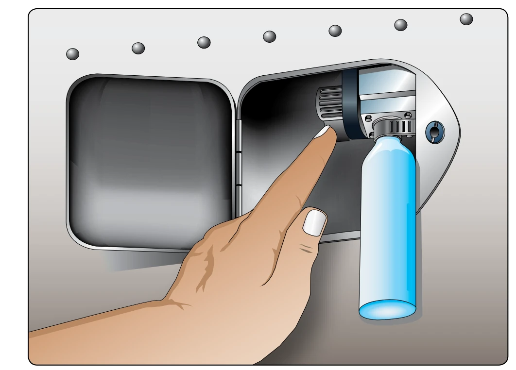
Repair of an oil tank usually requires that the tank be removed. The removal and installation procedures normally remain the same regardless of whether the engine is removed or not. First, the oil must be drained. Most light aircraft provide an oil drain similar to that shown in Figure 6-19. On some aircraft, the normal ground attitude of the aircraft may prevent the oil tank from draining completely. If the amount of undrained oil is excessive, the aft portion of the tank can be raised slightly after the tank straps have been loosened to complete the drainage.