
Chapter 6
Lubrication & Cooling Systems
Oil Cooler
The cooler, either cylindrical or elliptical shaped, consists of a core enclosed in a double-walled shell. The core is built of copper or aluminum tubes with the tube ends formed to a hexagonal shape and joined together in the honeycomb effect. [Figure 6-11] The ends of the copper tubes of the core are soldered, whereas aluminum tubes are brazed or mechanically joined. The tubes touch only at the ends so that a space exists between them along most of their lengths. This allows oil to flow through the spaces between the tubes while the cooling air passes through the tubes.
The space between the inner and outer shells is known as
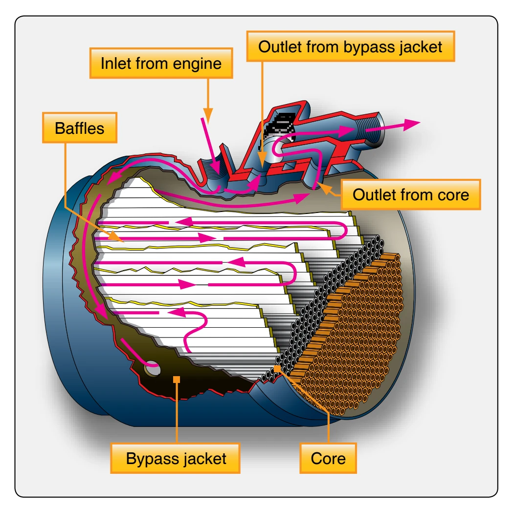
the annular or bypass jacket. Two paths are open to the flow of oil through a cooler. From the inlet, it can flow halfway around the bypass jacket, enter the core from the bottom, and then pass through the spaces between the tubes and out to the oil tank. This is the path the oil follows when it is hot enough to require cooling. As the oil flows through the core, it is guided by baffles that force the oil to travel back and forth several times before it reaches the core outlet. The oil can also pass from the inlet completely around the bypass jacket to the outlet without passing through the core. Oil follows this bypass route when the oil is cold or when the core is blocked with thick, congealed oil.
Oil Cooler Flow Control Valve
As discussed previously, the viscosity of the oil varies with its temperature. Since the viscosity affects its lubricating properties, the temperature at which the oil enters an engine must be held within close limits. Generally, the oil leaving an engine must be cooled before it is recirculated. Obviously, the amount of cooling must be controlled if the oil is to return to the engine at the correct temperature. The oil cooler flow control valve determines which of the two possible paths the oil takes through the oil cooler. [Figure 6-12]
There are two openings in a flow control valve that fit over the corresponding outlets at the top of the cooler. When the oil is cold, a bellows within the flow control contracts and lifts a valve from its seat. Under this condition, oil entering the cooler has a choice of two outlets and two paths. Following the path of least resistance, the oil flows around the jacket and out past the thermostatic valve to the tank. This allows the oil to warm up quickly and, at the same time, heats the
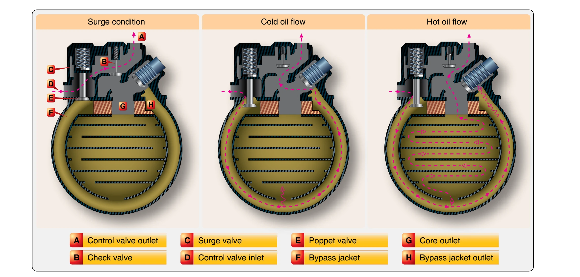
oil in the core. As the oil warms up and reaches its operating temperature, the bellows of the thermostat expand and closes the outlet from the bypass jacket. The oil cooler flow control valve, located on the oil cooler, must now flow oil through the core of the oil cooler. No matter which path it takes through the cooler, the oil always flows over the bellows of the thermostatic valve. As the name implies, this unit regulates the temperature by either cooling the oil or passing it on to the tank without cooling, depending on the temperature at which it leaves the engine.
Surge Protection Valves
When oil in the system is congealed, the scavenger pump may build up a very high pressure in the oil return line. To prevent this high pressure from bursting the oil cooler or blowing off the hose connections, some aircraft have surge protection valves in the engine lubrication systems. One type of surge valve is incorporated in the oil cooler flow control valve; another type is a separate unit in the oil return line. [Figure 6-12]
The surge protection valve incorporated in a flow control valve is the more common type. Although this flow control valve differs from the one just described, it is essentially the same except for the surge protection feature. The highpressure operation condition is shown in Figure 6-12, in which the high oil pressure at the control valve inlet has forced the surge valve (C) upward. Note how this movement has opened the surge valve and, at the same time, seated the poppet valve (E). The closed poppet valve prevents oil from entering the cooler proper; therefore, the scavenge oil passes directly to the tank through outlet (A) without passing through either the cooler bypass jacket or the core. When the pressure drops to a safe value, the spring forces the surge and poppet valves downward, closing the surge valve (C) and opening the poppet valve (E). Oil then passes from the control valve inlet (D), through the open poppet valve, and into the bypass jacket (F). The thermostatic valve, according to oil temperature, determines oil flow either through the bypass jacket to port (H) or through the core to port (G). The check valve (B) opens to allow the oil to reach the tank return line.
Airflow Controls
By regulating the airflow through the cooler, the temperature of the oil can be controlled to fit various operating conditions. For example, the oil reaches operating temperature more quickly if the airflow is cut off during engine warm-up. There are two methods in general use: shutters installed on the rear of the oil cooler, and a flap on the air-exit duct. In some cases, the oil cooler air-exit flap is opened manually and closed by a linkage attached to a flight deck lever. More often, the flap is opened and closed by an electric motor.
One of the most widely used automatic oil temperature control devices is the floating control thermostat that provides manual and automatic control of the oil inlet temperatures. With this type of control, the oil cooler air-exit door is opened and closed automatically by an electrically operated actuator. Automatic operation of the actuator is determined by electrical impulses received from a controlling thermostat inserted in the oil pipe leading from the oil cooler to the oil supply tank. The actuator may be operated manually by an oil cooler air-exit door control switch. Placing this switch in the “open” or “closed” position produces a corresponding movement of the cooler door. Placing the switch in the “auto” position puts the actuator under the automatic control of the floating control thermostat. [Figure 6-13] The thermostat shown in Figure 6-13 is adjusted to maintain a normal oil temperature so that it does not vary more than approximately 5° to 8 °C, depending on the installation.
During operation, the temperature of the engine oil flowing over the bimetal element causes it to wind or unwind slightly. [Figure 6-13B] This movement rotates the shaft (A) and the grounded center contact arm (C). As the grounded contact arm is rotated, it is moved toward either the open or closed floating contact arm (G). The two floating contact arms are oscillated by the cam (F), which is continuously rotated by an electric motor (D) through a gear train (E). When the grounded center contact arm is positioned by the bimetal element so that it touches one of the floating contact arms, an electric circuit to the oil cooler exit-flap actuator motor is completed, causing the actuator to operate and position the oil cooler air-exit flap. Newer systems use electronic control systems, but the function or the overall operation is basically the same regarding control of the oil temperature through control of the air flow through the cooler.
In some lubrication systems, dual oil coolers are used. If the typical oil system previously described is adapted to two oil coolers, the system is modified to include a flow divider, two identical coolers and flow regulators, dual air-exit doors, a two-door actuating mechanism, and a Y-fitting. [Figure 6-14] Oil is returned from the engine through a single tube to the flow divider (E), where the return oil flow is divided equally into two tubes (C), one for each cooler. The coolers and regulators have the same construction and operations as the cooler and flow regulator just described. Oil from the coolers is routed through two tubes (D) to a Y-fitting, where the floating control thermostat (A) samples oil temperature and positions the two oil cooler air-exit doors through the use of a two-door actuating mechanism. From the Y-fitting, the lubricating oil is returned to the tank where it completes its circuit.
Dry Sump Lubrication System Operation
The following lubrication system is typical of those on small, single-engine aircraft. The oil system and components are those used to lubricate a 225 horsepower (hp) six-cylinder, horizontally opposed, air-cooled engine. In a typical dry sump pressure-lubrication system, a mechanical pump supplies oil under pressure to the bearings throughout the engine. [Figure 6-4] The oil flows into the inlet or suction side of the oil pump through a suction screen and a line connected to the external tank at a point higher than the bottom of the oil sump. This prevents sediment that falls into the sump from being drawn into the pump. The tank outlet is higher than the pump inlet, so gravity can assist the flow into the pump. The engine-driven, positive-displacement, gear-type pump forces the oil into the full flow filter. [Figure 6-6] The oil either passes through the filter under normal conditions or, if the filter were to become clogged, the filter bypass valve would open as mentioned earlier. In the bypass position, the oil would not be filtered. As seen in Figure 6-6, the regulating (relief) valve senses when system pressure is reached and opens enough to bypass oil to the inlet side of the oil pump. Then, the oil flows into a manifold that distributes the oil