
Chapter 6
Lubrication & Cooling Systems
The oil filter used on an aircraft engine is usually one of four types: screen, Cuno, canister, or spin-on. A screen-type filter with its double-walled construction provides a large filtering area in a compact unit. [Figure 6-6] As oil passes through the fine-mesh screen, dirt, sediment, and other foreign matter are removed and settle to the bottom of the housing. At regular intervals, the cover is removed, and the screen and housing cleaned with a solvent. Oil screen filters are used mostly as suction filters on the inlet of the oil pump.
The Cuno oil filter has a cartridge made of discs and spacers. A cleaner blade fits between each pair of discs. The cleaner blades are stationary, but the discs rotate when the shaft is turned. Oil from the pump enters the cartridge well that surrounds the cartridge and passes through the spaces between the closely spaced discs of the cartridge, then through the hollow center, and on to the engine. Any foreign particles in the oil are deposited on the outer surface of the cartridge. When the cartridge is rotated, the cleaner blades comb the foreign matter from the discs. The cartridge of the manually operated Cuno filter is turned by an external handle. Automatic Cuno filters have a hydraulic motor built into the filter head. This motor, operated by engine oil pressure, rotates the cartridge whenever the engine is running. There is a manual turning nut on the automatic Cuno filter for rotating the cartridge manually during inspections. This filter is not often used on modern aircraft.
A canister housing filter has a replaceable filter element that is replaced with the rest of the components other than seals and gaskets being reused. [Figure 6-7] The filter element is designed with a corrugated, strong steel center
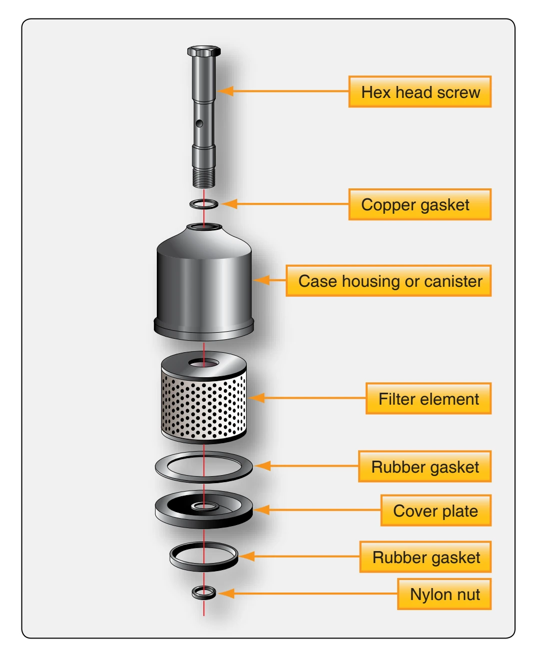
tube supporting each convoluted pleat of the filter media, resulting in a higher collapse pressure rating. The filter provides excellent filtration, because the oil flows through many layers of locked-in-fibers.
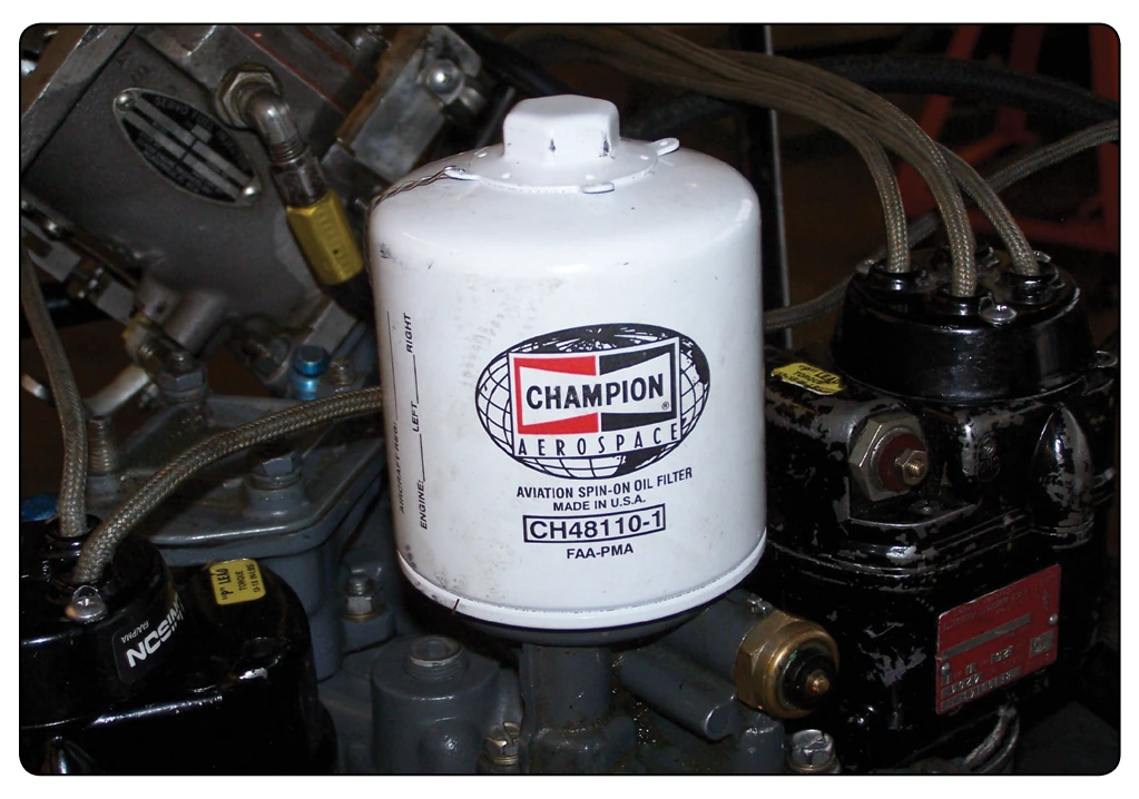
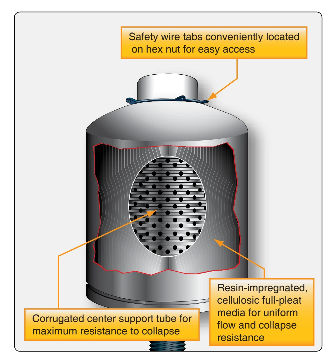
Full flow spin-on filters are the most widely used oil filters for reciprocating engines. [Figure 6-8] Full flow means that all the oil is normally passed through the filter. In a full flow system, the filter is positioned between the oil pump and the engine bearings, which filters the oil of any contaminants before they pass through the engine bearing surfaces. The filter also contains an antidrain back valve and a pressure relief valve, all sealed in a disposable housing. The relief valve is used in case the filter becomes clogged. It would open to allow the oil to bypass, preventing the engine components from oil starvation. A cutaway of the micronic filter element shows the resin-impregnated cellulosic full-pleat media that is used to trap harmful particles, keeping them from entering the engine. [Figure 6-9]
Oil Pressure Regulating Valve
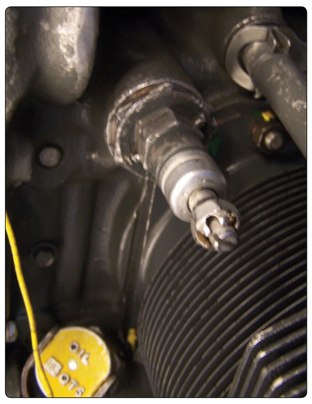
An oil pressure regulating valve limits oil pressure to a predetermined value, depending on the installation. [Figure 6-6] This valve is sometimes referred to as a relief valve, but its real function is to regulate the oil pressure at a preset pressure level. The oil pressure must be sufficiently high to ensure adequate lubrication of the engine and its
accessories at high speeds and powers. This pressure helps ensure that the oil film between the crankshaft journal and bearing is maintained. However, the pressure must not be too high, as leakage and damage to the oil system may result. The oil pressure is generally adjusted by loosening the locknut and turning the adjusting screw. [Figure 6-10] On most aircraft engines, turning the screw clockwise increases the tension of the spring that holds the relief valve on its seat and increases the oil pressure; turning the adjusting screw counterclockwise decreases the spring tension and lowers the pressure. Some engines use washers under the spring that are either removed or added to adjust the regulating valve and pressure. The oil pressure should be adjusted only after the engine’s oil is at operating temperature and the correct viscosity is verified. The exact procedure for adjusting the oil pressure and the factors that vary an oil pressure setting are included in applicable manufacturer’s instructions.
Oil Pressure Gauge
Usually, the oil pressure gauge indicates the pressure that oil enters the engine from the pump. This gauge warns of possible engine failure caused by an exhausted oil supply, failure of the oil pump, burned-out bearings, ruptured oil lines, or other causes that may be indicated by a loss of oil pressure.
One type of oil pressure gauge uses a Bourdon-tube mechanism that measures the difference between oil pressure and cabin, or atmospheric, pressure. This gauge is constructed similarly to other Bourdon-type gauges, except that it has a small restriction built into the instrument case, or into the nipple connection leading to the Bourdon tube. This restriction prevents the surging action of the oil pump from damaging the gauge or causing the pointer to oscillate too violently with each pressure pulsation. The oil pressure gauge has a scale ranging from 0–200 psi, or from 0–300 psi. Operation range markings are placed on the cover glass, or the face of the gauge, to indicate the safe range of oil pressure for a given installation.
A dual-type oil pressure gauge is available for use on
multiengine aircraft. The dual indicator contains two Bourdon tubes, housed in a standard instrument case; one tube being used for each engine. The connections extend from the back of the case to each engine. There is one common movement assembly, but the moving parts function independently. In some installations, the line leading from the engine to the pressure gauge is filled with light oil. Since the viscosity of this oil does not vary much with changes in temperature, the gauge responds better to changes in oil pressure. In time, engine oil mixes with some of the light oil in the line to the transmitter; during cold weather, the thicker mixture causes sluggish instrument readings. To correct this condition, the gauge line must be disconnected, drained, and refilled with light oil.
The current trend is toward electrical transmitters and indicators for oil and fuel pressure-indicating systems in all aircraft. In this type of indicating system, the oil pressure being measured is applied to the inlet port of the electrical transmitter where it is conducted to a diaphragm assembly by a capillary tube. The motion produced by the diaphragm’s expansion and contraction is amplified through a lever and gear arrangement. The gear varies the electrical value of the indicating circuit, which in turn, is reflected on the indicator in the flight deck. This type of indicating system replaces long fluid-filled tubing lines with an almost weightless piece of wire.
Oil Temperature Indicator
In dry-sump lubricating systems, the oil temperature bulb may be anywhere in the oil inlet line between the supply tank and the engine. Oil systems for wet-sump engines have the temperature bulb located where it senses oil temperature after the oil passes through the oil cooler. In either system, the bulb is located so that it measures the temperature of the oil before it enters the engine’s hot sections. An oil temperature gauge in the flight deck is connected to the oil temperature bulb by electrical leads. The oil temperature is indicated on the gauge. Any malfunction of the oil cooling system appears as an abnormal reading.