Chapter 9
Engine Fire Protection Systems
Engine Fire Protec
Introduction
Because fire is one of the most dangerous threats to an aircraft, the potential fire zones of all multiengine aircraft currently produced are protected by a fixed fire protection system. A “fire zone” is an area or region of an aircraft designated by the manufacturer to require fire detection and/or fire extinguishing equipment and a high degree of inherent fire resistance. The term “fixed” describes a permanently installed system in contrast to any type of portable fire extinguishing equipment, such as a hand-held fire extinguisher.
In accordance with Title 14 of the Code of Federal Regulations (14 CFR) parts 23 and 25, engine fire protection systems are mandatory on: multiengine turbine-powered aircraft, multiengine reciprocating engine-powered aircraft incorporating turbochargers, aircraft with engine(s) located where they are not readily visible from the flight deck, all commuter and transport category aircraft, and the auxiliary power unit (APU) compartment of any aircraft incorporating an APU. Fire protection systems are not mandatory for many single and twin reciprocating engine general aviation (GA) aircraft.
Several general failures or hazards can result in overheat conditions or fires peculiar to turbine engine aircraft because of their operating characteristics. The two major types of turbine failure can be classified as 1) thermodynamic and
- mechanical.
Thermodynamic causes upset the proportion of air used to cool combustion temperatures to the levels that the turbine materials can tolerate. When the cooling cycle is upset, turbine blades can melt, causing a sudden loss of thrust. The rapid buildup of ice on inlet screens or inlet guide vanes can result in severe overheating, causing the turbine blades to melt or to be severed and thrown outward. Such failure can result in a severed tail cone and possible penetration of the aircraft structure, tanks, or equipment near the turbine wheel. In general, most thermodynamic failures are caused by ice, excess air bleed or leakage, or faulty controls that permit compressor stall or excess fuel.
Mechanical failures, such as fractured or thrown blades, can also lead to overheat conditions or fires. Thrown blades can puncture the tail cone, creating an overheat condition. Failure of forward stages of multi-stage turbines is usually ction Systems
much more severe. Penetration of the turbine case by failed blades is a possible fire hazard, as is the penetration of lines and components containing flammable fluids.
A high flow of fuel through an improperly adjusted fuel nozzle can cause burn-through of the tail cone in some engines. Engine fires can be caused by burning fluid that occasionally runs out through the exhaust pipe.
Components
A complete fire protection system includes both a fire detection and a fire extinguishing system. To detect fires or overheat conditions, detectors are placed in the various zones to be monitored. Fires are detected in aircraft by using one or more of the following: overheat detectors, rate-oftemperature-rise detectors, and flame detectors. In addition to these methods, other types of detectors are used in aircraft fire protection systems but are not used to detect engine fires. For example, smoke detectors are better suited to monitor areas such as baggage compartments or lavatories, where materials burn slowly or smolder. Other types of detectors in this category include carbon monoxide detectors.
Fire protection systems on current-production aircraft do not rely on observation by crewmembers as a primary method of fire detection. An ideal fire detector system includes as many of the following features as possible:
- A system that does not cause false warnings under any flight or ground condition.
- Rapid indication of a fire and accurate location of the fire.
- Accurate indication that a fire is out.
- Indication that a fire has reignited.
- Continuous indication for duration of a fire.
- Means for electrically testing the detector system from the aircraft flight deck.
- Detectors that resist damage from exposure to oil, water, vibration, extreme temperatures, or handling.
- Detectors that are light in weight and easily adaptable to any mounting position.
- Detector circuitry that operates directly from the aircraft power system without inverters.
- Minimum electrical current requirements when not indicating a fire.
- Each detector system should turn on a flight deck light, indicating the location of the fire, and have an audible alarm system.
- A separate detector system for each engine.
Engine Fire Detection Systems
Several different types of fire detection systems are installed in aircraft to detect engine fires. Two common types used are spot detectors and continuously loop systems. Spot detector systems use individual sensors to monitor a fire zone. Examples of spot detector systems are the thermal switch system, the thermocouple system, the optical fire detection system, and the pneumatic-based thermal fire detection system. Continuous loop systems are typically installed on transport type aircraft and provide more complete fire detection coverage by using several loop-type sensors.
Thermal Switch System
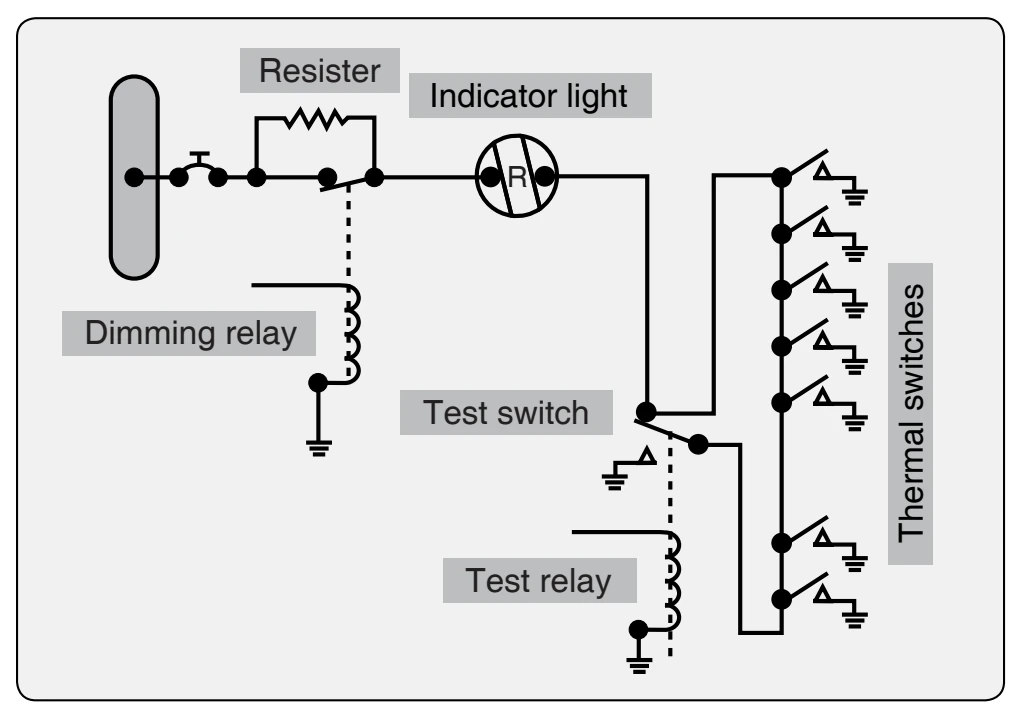
A number of detectors or sensing devices are available. Many older model aircraft still operating have some type of thermal switch system or thermocouple system. A thermal switch system has one or more lights energized by the aircraft power system and thermal switches that control operation of the light(s). These thermal switches are heat-sensitive units that complete electrical circuits at a certain temperature. They are connected in parallel with each other, but in series with the indicator lights [Figure 9-1]. If the temperature rises above a set value in any one section of the circuit, the thermal switch closes, completing the light circuit to indicate a fire or overheat condition.
No set number of thermal switches is required; the exact number usually is determined by the aircraft manufacturer. On some installations, all the thermal detectors are connected to one light; others may have a separate thermal switch for each indicator light.