
Chapter 9
Engine Fire Protection Systems
Large commercial aircraft almost exclusively use continuous thermal sensing elements for powerplant protection, since these systems offer superior detection performance and coverage, and they have the proven ruggedness to survive in the harsh environment of modern turbofan engines.
A continuous-loop detector, or sensing system, permits more complete coverage of a fire hazard area than any of the spot-type temperature detectors. Continuous-loop systems are versions of the thermal switch system. They are overheat systems, heat-sensitive units that complete electrical circuits at a certain temperature. There is no rate-of-heatrise sensitivity in a continuous-loop system. Two widely used types of continuous-loop systems are the Kidde and the Fenwal systems. This text briefly discusses the Fenwal system, while the Kidde system is discussed more in-depth.
Fenwal Continuous-Loop System The Fenwal system uses a slender inconel tube packed with thermally sensitive eutectic salt and a nickel wire center
conductor. [Figure 9-4] Lengths of these sensing elements are connected in series to a control unit. The elements may be of equal or varying length and of the same or different temperature settings. The control unit, operating directly from the power source, impresses a small voltage on the sensing elements. When an overheat condition occurs at any point along the element length, the resistance of the eutectic salt within the sensing element drops sharply, causing current to flow between the outer sheath and the center conductor. This
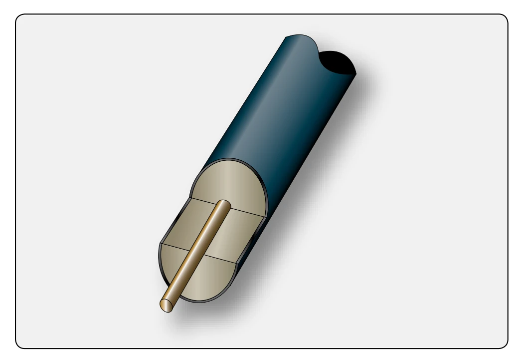
current flow is sensed by the control unit, which produces a signal to actuate the output relay.
When the fire has been extinguished or the critical temperature lowered, the Fenwal system automatically returns to standby alert, ready to detect any subsequent fire or overheat condition. The Fenwal system may be wired to employ a “loop” circuit. In this case, should an open circuit occur, the system still signals fire or overheat. If multiple open circuits occur, only that section between breaks becomes inoperative.
Kidde Continuous-Loop System In the Kidde continuous-loop system, two wires are imbedded in an inconel tube filled with a thermistor core material. [Figure 9-5] Two electrical conductors go through the length of the core. One conductor has a ground connection to the tube and the other conductor connects to the fire detection control unit.
As the temperature of the core increases, electrical resistance to ground decreases. The fire detection control unit monitors this resistance. If the resistance decreases to the overheat set point, an overheat indication occurs in the flight deck. Typically, a 10-second time delay is incorporated for the
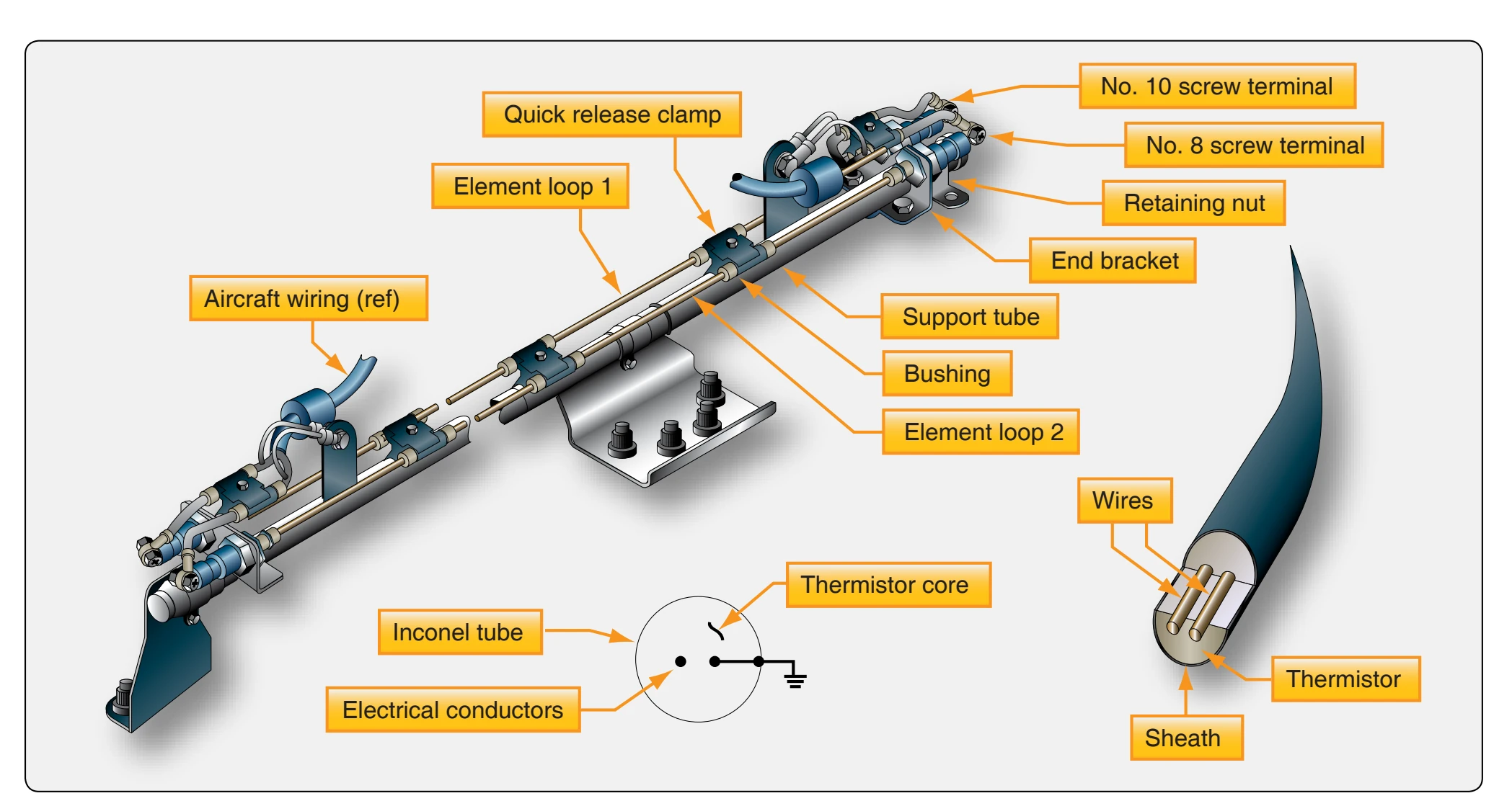
overheat indication. If the resistance decreases more to the fire set point, a fire warning occurs. When the fire or overheat condition is gone, the resistance of the core material increases to the reset point and the flight deck indications go away.
The rate of change of resistance identifies an electrical short or a fire. The resistance decreases more quickly with an electrical short than with a fire. In addition to fire and overheat detection, the Kidde continuous-loop system can supply nacelle temperature data to the aircraft condition monitoring function of the Aircraft In-Flight Monitoring System (AIMS).
Sensing Element The sensing element consists, essentially, of an infinite number of unit thermistors electrically in parallel along its length. The resistance of the sensing element is a function of the length heated, as well as the temperature-heating of less than the full length of element, which requires that portion to be heated to a higher temperature to achieve the same total resistance change. As a result, the system responds not to a fixed alarm temperature but to the sum of the resistances (in parallel) that reflects a nonarithmetic “average.” The sensing element may be routed close to nonhazardous hot spots that may have a normal temperature well above the overall alarm temperature, without danger of causing a false alarm. This feature permits the alarm point to be set close to the maximum general ambient temperature, giving greater sensitivity to a general overheat or fire without being subject to false alarms from localized nonhazardous hot spots.
Combination Fire & Overheat Warning The analog signal from the thermistor sensing element permits the control circuits to be arranged to give a two-level response from the same sensing element loop. The first is an overheat
Temperature Trend Indication The analog signal produced by the sensing element loop as its temperature changes can readily be converted to signals suitable for meter or cathode ray tube (CRT) display to indicate engine bay temperature increases from normal. A comparison of the readings from each loop system also provides a check on the condition of the fire detection system, because the two loops should normally read alike.
System Test The integrity of the continuous-loop fire detection system may be tested by actuating a test switch in the flight deck, which switches one end of the sensing element loop from its control circuit to a test circuit, built into the control unit, that simulates the sensing element resistance change due to fire. [Figure 9-6] If the sensing element loop is unbroken, the resistance detected “seen” by the control circuit is now
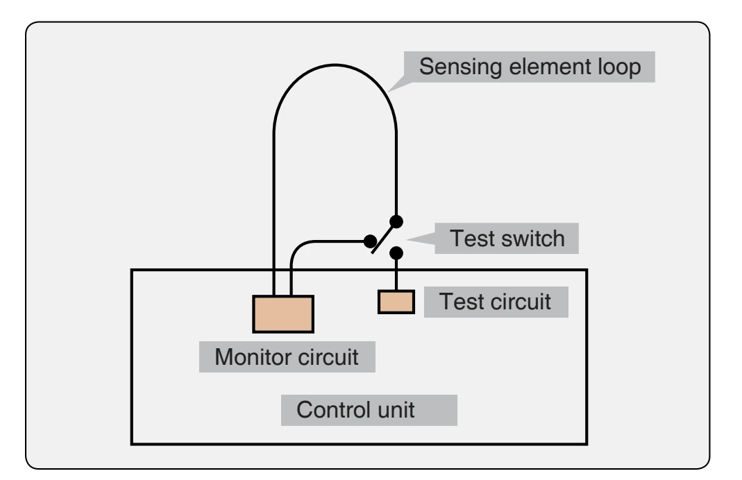
that of the simulated fire and so the alarm is signaled. This demonstrates, in addition to the continuity of the sensing element loop, the integrity of the alarm indicator circuit and the proper functioning of the control circuits. The thermistor properties of the sensing element remain unchanged for the life of the element (no chemical or physical changes take place on heating), so that it functions properly as long as it is electrically connected to the control unit.