
Chapter 9
Engine Fire Protection Systems
Some warning lights are push-to-test lights. The bulb is tested by pushing it in to check an auxiliary test circuit. The circuit shown in Figure 9-1 includes a test relay. With the relay contact in the position shown, there are two possible paths for current flow from the switches to the light. This is an additional safety feature. Energizing the test relay completes a series circuit and checks all the wiring and the light bulb.
Also included in the circuit shown in Figure 9-1 is a dimming relay. By energizing the dimming relay, the circuit is altered to include a resistor in series with the light. In some installations, several circuits are wired through the dimming relay, and all the warning lights may be dimmed at the same time.
Thermocouple Systems
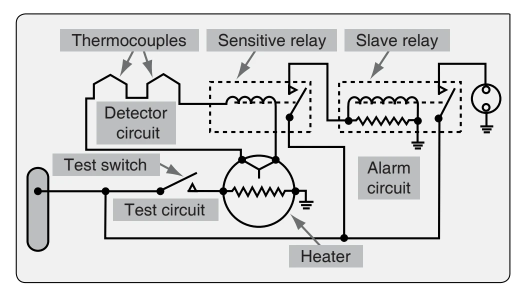
The thermocouple fire warning system operates on an entirely different principle than the thermal switch system. A thermocouple depends on the rate of temperature rise and does not give a warning when an engine slowly overheats or a short circuit develops. The system consists of a relay box, warning lights, and thermocouples. The wiring system of these units may be divided into the following circuits: (1) the detector circuit, (2) the alarm circuit, and (3) the test circuit. These circuits are shown in Figure 9-2.
The relay box contains two relays, the sensitive relay and the slave relay, and the thermal test unit. Such a box may contain from one to eight identical circuits, depending on the number of potential fire zones. The relays control the warning lights. In turn, the thermocouples control the operation of the relays. The circuit consists of several thermocouples in series with each other and with the sensitive relay.
Thermocouple leads are made from a variety of metals, depending on the maximum temperature to which they are exposed. Iron and constantan, or copper and constantan, are common for CHT measurement. Chromel and alumel are used for turbine EGT thermocouples. The point where these metals are joined and exposed to the heat of a fire is called a hot junction. There is also a reference junction enclosed in a dead air space between two insulation blocks.
A metal cage surrounds the thermocouple to give mechanical protection without hindering the free movement of air to the hot junction. Thermocouple leads are designed for a specific installation and may not be altered, if they are altered they will no longer be calibrated specific probe and instrument combination.
If the temperature rises rapidly, the thermocouple produces a voltage because of the temperature difference between the reference junction and the hot junction. If both junctions are heated at the same rate, no voltage results. In the engine compartment, there is a normal, gradual rise in temperature from engine operation; because it is gradual, both junctions heat at the same rate and no warning signal is given.
If there is a fire, however, the hot junction heats more rapidly than the reference junction. The reference junction is also commonly referred to as the cold junction. The ensuing voltage causes a current to flow within the detector circuit. Any time the current is greater than 4 milliamperes (0.004 ampere), the sensitive relay closes. This completes a circuit from the aircraft power system to the coil of the slave relay. The slave relay then closes and completes the circuit to the
The total number of thermocouples used in individual detector circuits depends on the size of the fire zones and the total circuit resistance, which usually does not exceed 5 ohms. As shown in Figure 9-2, the circuit has two resistors. The resistor connected across the slave relay terminals absorbs the coil’s self-induced voltage to prevent arcing across the points of the sensitive relay. The contacts of the sensitive relay are so fragile that they burn or weld if arcing is permitted.
When the sensitive relay opens, the circuit to the slave relay is interrupted and the magnetic field around its coil collapses. When this happens, the coil gets a voltage through self-induction, but with the resistor across the coil terminals, there is a path for any current flow as a result of this voltage. Thus, arcing at the sensitive relay contacts is eliminated.
Optical Fire Detection Systems
Optical sensors, often referred to as “flame detectors,” are designed to alarm when they detect the presence of prominent, specific radiation emissions from hydrocarbon flames. The two types of optical sensors available are infrared (IR) and ultraviolet, based on the specific emission wave lengths they are designed to detect.
Infrared Optical Fire Protection IR-based optical flame detectors are used primarily on light turboprop aircraft and helicopter engines. These sensors have proven to be very dependable and economical for the relatively benign environments of these applications.
Principle of Operation Radiation emitted by the fire crosses the airspace between the fire and the detector and impinges on the detector front face and window. The window allows a broad spectrum of radiation to pass into the detector where it impinges on the face of the sensing device filter. The filter allows only radiation in a tight waveband centered around 4.3 micrometers in the IR to pass on to the radiation-sensitive surface of the sensing device. The radiation striking the sensing device minutely raises its temperature causing small thermoelectric voltages to be generated. These voltages are fed to an amplifier whose output is connected to various analytical electronic processing circuits. The processing electronics is tailored exactly to the time signature of all known hydrocarbon flame sources and ignores false alarm sources, such as incandescent lights and sunlight. Alarm sensitivity level is accurately controlled by a digital circuit. A typical warning system is illustrated in Figure 9-3.
Pneumatic Thermal Fire Detection
Pneumatic detectors are based on the principles of gas laws. The sensing element consists of a closed helium-filled tube connected at one end to a responder assembly. As the element is heated, the gas pressure inside the tube increases until the alarm threshold is reached. At this point, an internal switch closes and reports an alarm to the flight deck. The pneumatic detector integrity pressure switch opens and triggers the fault alarm if the pneumatic detector losses pressure, as in the case of a leak.