
Chapter 9
Engine Fire Protection Systems
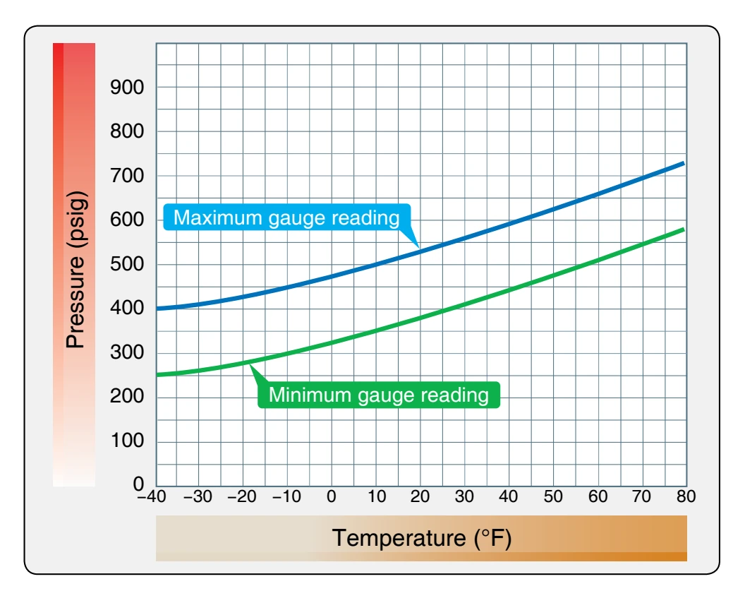
Fire extinguisher containers are checked periodically to determine that the pressure is between the prescribed minimum and maximum limits. Changes of pressure with ambient temperatures must also fall within prescribed limits. The graph shown in Figure 9-18 is typical of the pressure temperature curve graphs that provide maximum and minimum gauge readings. If the pressure does not fall within the graph limits, the extinguisher container is replaced. The service life of fire extinguisher discharge cartridges is calculated from the manufacturer’s date stamp, which is usually placed on the face of the cartridge. The cartridge service life recommended by the manufacturer is usually in terms of years. Cartridges are available with a service life of 5 years or more. To determine the unexpired service life of a discharge cartridge, it is usually necessary to remove the electrical leads and discharge line from the plug body, which can then be removed from the extinguisher container.
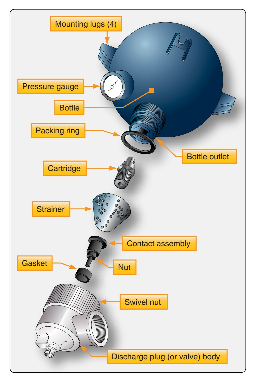
Be careful when replacing cartridge and discharge valves. Most new extinguisher containers are supplied with their cartridge and discharge valve disassembled. Before installation on the aircraft, properly assemble the cartridge in the discharge valve and connect the valve to the container, usually by means of a swivel nut that tightens against a packing ring gasket. [Figure 9-19]
If a cartridge is removed from a discharge valve for any reason, it should not be used in another discharge valve assembly, since the distance the contact point protrudes may vary with each unit. Thus, continuity might not exist if a used plug that had been indented with a long contact point were installed in a discharge valve with a shorter contact point.
The preceding material in this chapter is general in nature, addressing the principles involved and general procedures to be followed. When actually performing maintenance, always refer to the applicable maintenance manuals and other related publications pertaining to a particular aircraft.
Boeing 777 Aircraft Fire Detection & Extinguishing System
The following section discusses the fire detection and extinguishing system of the B777 aircraft. The information is included only for familiarization purposes.
Each engine has two fire detection loops: loop 1 and loop
- A fire detection card in the system card file monitors the loops for fires, overheat conditions, and faults. There is a fire detection card for each engine.
Overheat Detection
If the fire detection loops detect an overheat condition, the fire detection card sends a signal to the AIMS and to the
- The master caution lights come on.
- The caution aural operates.
- An engine overheat caution message shows.
Fire Detection
If an engine fire occurs, the fire detection card sends a signal to the AIMS and to the warning electronics unit, and a warning message illuminates. The following indications occur in the flight deck:
- The master warning lights come on.
- The fire warning aural operates.
- An engine fire warning message shows.
- The engine fire warning light comes on.
- The fuel control switch fire warning light comes on.
Nacelle Temperature Recording
The fire detection card measures the average temperature of the loops. This data goes to the AIMS through the system’s ARINC 629 buses and is recorded by the aircraft condition monitoring function.