
Chapter 2
Aerodynamics of Flight
Rearward Flight
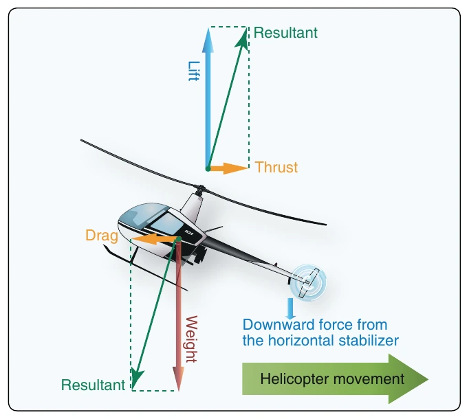
For rearward flight, the tip-path plane is tilted rearward, which, in turn, tilts the lift-thrust vector rearward. Drag now acts forward with the lift component straight up and weight straight down. [Figure 2-44]
Pilots must be aware of the hazards of rearward flight. Because of the position of the horizontal stabilizer, the tail end of the helicopter tends to pitch downward in rearward flight, causing the probability of hitting the ground to be greater than in forward flight. Another factor to consider in rearward flight is skid design. Most helicopter skids are not turned upward in the back, and any contact with the ground during rearward flight can put the helicopter in an uncontrollable position leading to tail rotor contact with the ground. Pilots must do a thorough scan of the area before attempting to hover rearward, looking for obstacles and terrain changes. Slower airspeeds can help mitigate risk and maintain a higher-than-normal hover altitude.
Turning Flight
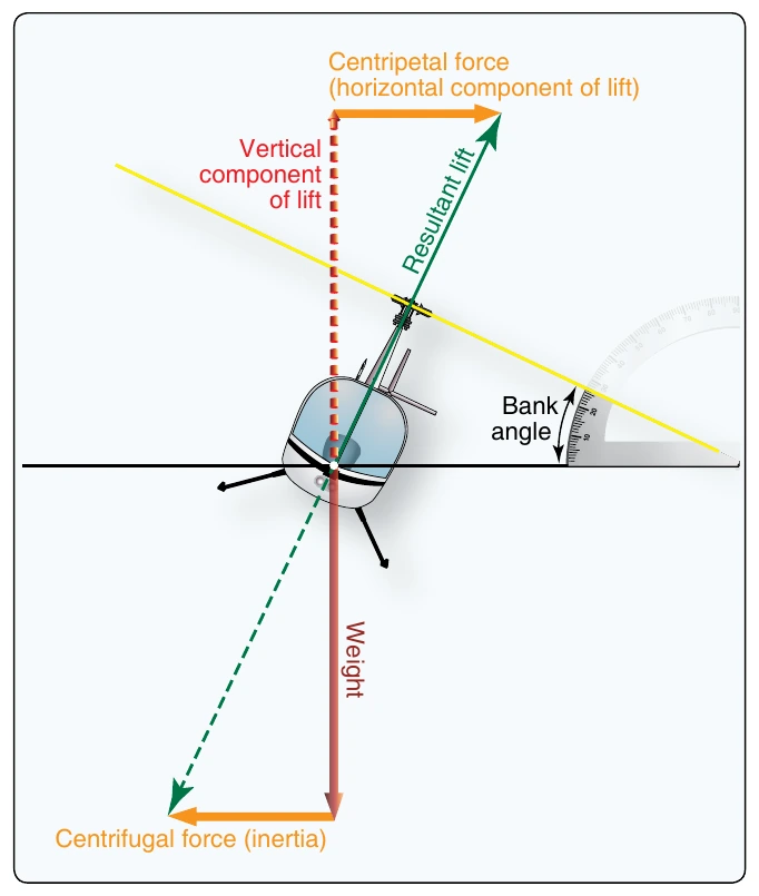
In forward flight, the rotor disk is tilted forward, which also tilts the total lift-thrust force of the rotor disk forward. When resulting in lift being separated into two components. Lift acting upward and opposing weight is called the vertical component of lift. Lift acting horizontally and opposing inertia (centrifugal force) is the horizontal component of lift (centripetal force). [Figure 2-45]
As the angle of bank increases, the total lift force is tilted more toward the horizontal, thus causing the rate of turn to increase because more lift is acting horizontally. Since the resultant lifting force acts more horizontally, the effect of lift acting the helicopter is banked, the rotor disk is tilted sideward vertically is decreased. To compensate for this decreased vertical lift, the AOA of the rotor blades must be increased in order to maintain altitude. The steeper the angle of bank is, the greater the AOA of the rotor blades required to maintain altitude. Thus, with an increase in bank and a greater AOA, the resultant lifting force increases, and the rate of turn is higher. Simply put, collective pitch must be increased in order to maintain altitude and airspeed while turning. Collective pitch controls the angle of incidence and along with other factors, determines the overall AOA in the rotor disk.
Autorotation
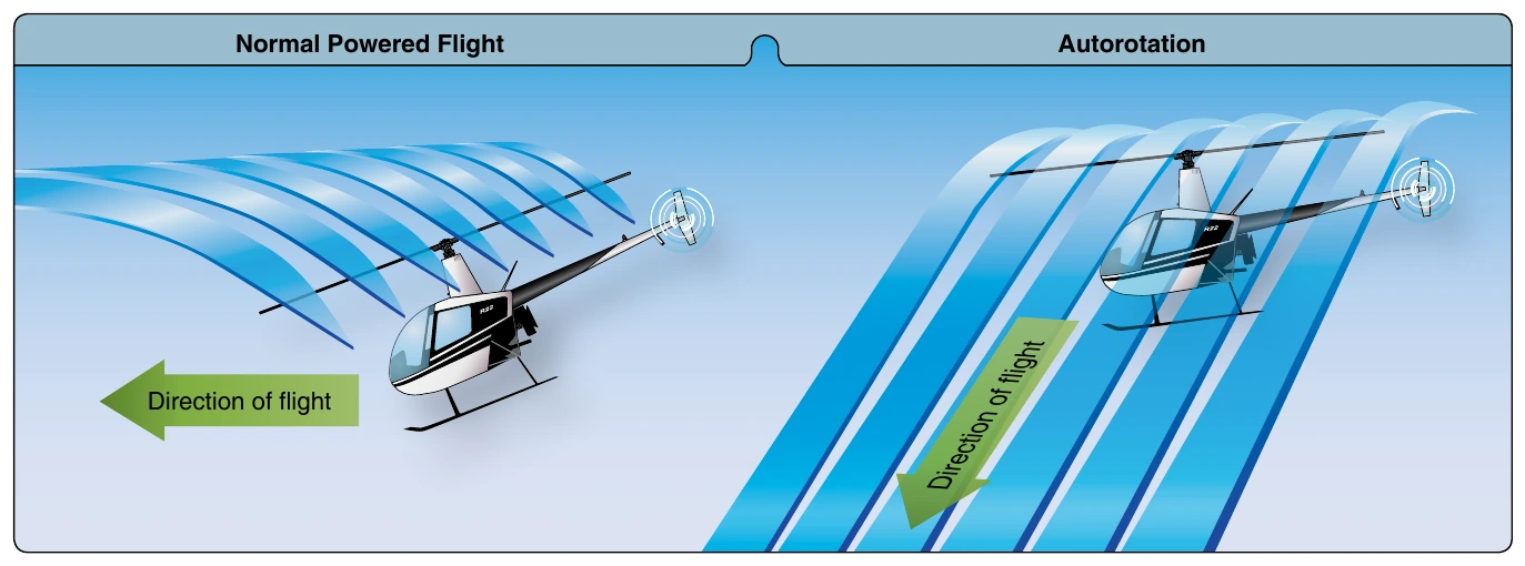
Autorotation is the state of flight where the main rotor disk of a helicopter is being turned by the action of air moving up through the rotor rather than engine power driving the rotor. In normal, powered flight, air is drawn into the main rotor disk from above and exhausted downward, but during autorotation, air moves up into the rotor disk from below as the helicopter descends. Autorotation is permitted mechanically by a freewheeling unit, which is a special clutch mechanism that allows the main rotor to continue turning even if the engine is not running. If the engine fails, the freewheeling unit automatically disengages the engine from the main rotor allowing the main rotor to rotate freely. It is the means by which a helicopter can be landed safely in the event of an engine failure; consequently, all helicopters must demonstrate this capability in order to be certified. [Figure 2-46] If a decision is made to attempt an engine restart in flight (the parameters for this emergency procedure will be different for each helicopter and must be precisely followed) the pilot must reengage the engine starter switch to start the engine. Once the engine is started, the freewheeling unit will reengage the engine with the main rotor.
Vertical Autorotation
Most autorotations are performed with forward speed. For simplicity, the following aerodynamic explanation is based on a vertical autorotative descent (no forward speed) in still air. Under these conditions, the forces that cause the blades to turn are similar for all blades regardless of their position in the plane of rotation. Therefore, dissymmetry of lift resulting from helicopter airspeed is not a factor.
During vertical autorotation, the rotor disk is divided into three regions (as illustrated in Figure 2-47): driven region, driving region, and stall region. Figure 2-48 shows three blade sections that illustrate force vectors. Part A is the driven region, B and D are points of equilibrium, part C is the driving region, and part E is the stall region. Force vectors are different in each region because rotational relative wind is slower near the blade root and increases continually toward the blade tip. Also, blade twist gives a more positive AOA in the driving region than in the driven region. The combination of the inflow up through the rotor with rotational relative wind produces different combinations of aerodynamic force at every point along the blade.
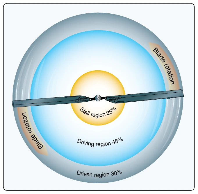
The driven region, also called the propeller region, is nearest the blade tips. Normally, it consists of about 30 percent of the radius. In the driven region, part A of Figure 2-48, the TAF acts behind the axis of rotation, resulting in an overall drag force. The driven region produces some lift, but that lift is offset by drag. The overall result is a deceleration in the rotation of the blade. The size of this region varies with the blade pitch, rate of descent, and rotor rpm. When changing autorotative rpm blade pitch, or rate of descent, the size of the driven region in relation to the other regions also changes.
There are two points of equilibrium on the blade—one between the driven region and the driving region, and one between the driving region and the stall region. At points of equilibrium, TAF is aligned with the axis of rotation. Lift and drag are produced, but the total effect produces neither acceleration nor deceleration.
The driving region, or autorotative region, normally lies between 25 to 70 percent of the blade radius. Part C of Figure 2-48 shows the driving region of the blade, which produces the forces needed to turn the blades during autorotation. Total aerodynamic force in the driving region is inclined slightly forward of the axis of rotation, producing a continual acceleration force. This inclination supplies thrust, which tends to accelerate the rotation of the blade. Driving region size varies with blade pitch setting, rate of descent, and rotor rpm.
By controlling the size of this region, a pilot can adjust autorotative rpm. For example, if the collective pitch is raised, the pitch angle increases in all regions. This causes the point of equilibrium to move inboard along the blade’s span, thus increasing the size of the driven region. The stall region also becomes larger while the driving region becomes smaller. Reducing the size of the driving region causes the acceleration force of the driving region and rpm to decrease. A constant rotor rpm is achieved by adjusting the collective pitch so blade acceleration forces from the driving region are balanced with the deceleration forces from the driven and stall regions.