Chapter 2
Aerodynamics of Flight
Bernoulli’s Principle
Bernoulli’s principle describes the relationship between internal fluid pressure and fluid velocity. It is a statement of the law of conservation of energy and helps explain why an airfoil develops an aerodynamic force. The concept of conservation of energy states energy cannot be created or destroyed and the amount of energy entering a system must also exit. Specifically, in this case the “energy” referred to is the dynamic pressure (the kinetic energy of the air— more velocity, more kinetic energy) and static air pressure (potential energy). These will change among themselves, but the total pressure energy remains constant inside the tube.
A simple tube with a constricted portion near the center of its length illustrates this principle. An example is running water through a garden hose. The mass of flow per unit area (cross-sectional area of tube) is the mass flow rate. In Figure 2-5, the flow into the tube is constant, neither accelerating nor decelerating; thus, the mass flow rate through the tube must be the same at stations 1, 2, and 3. If the cross-sectional area at any one of these stations—or any given point—in the tube is reduced, the fluid velocity must increase to maintain a constant mass flow rate to move the same amount of fluid through a smaller area. The continuity of mass flow causes the air to move faster through the venturi. In other words, fluid speeds up in direct proportion to the reduction in area.
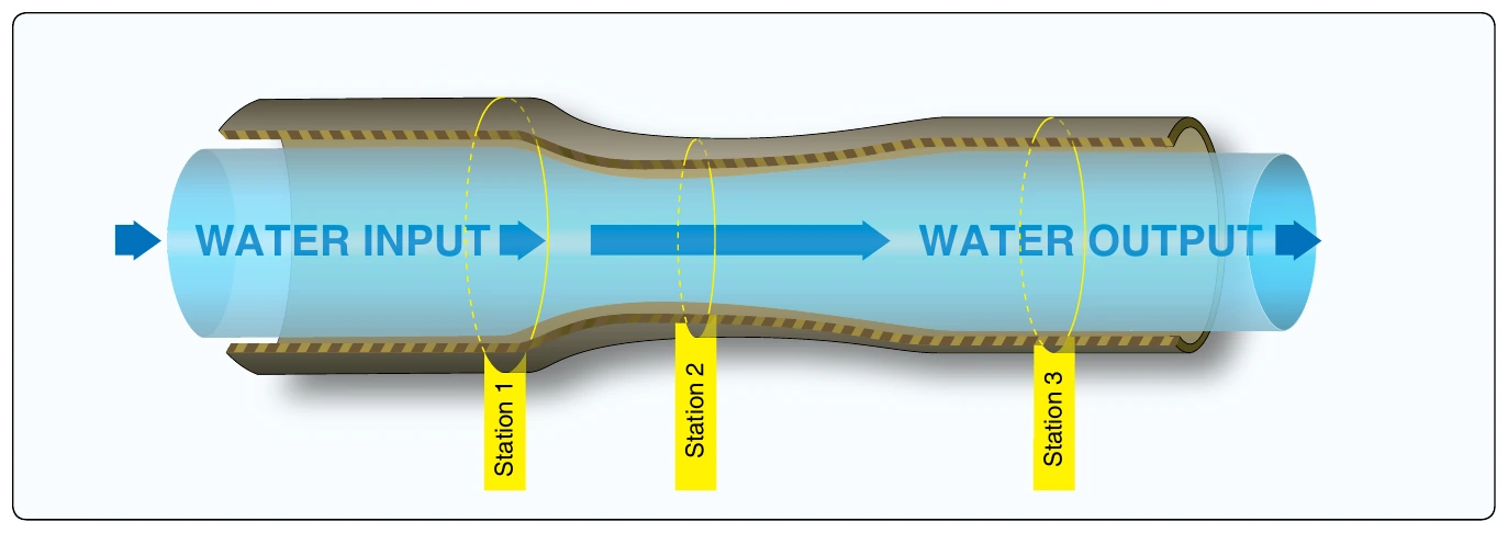
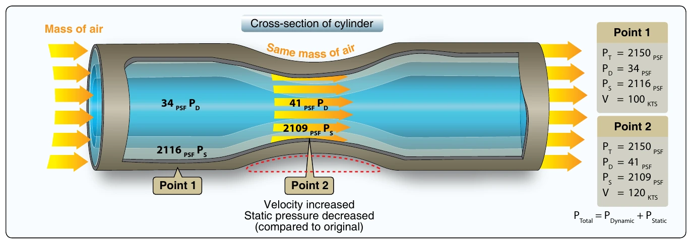
Bernoulli (Ptotal = Pdynamic + Pstatic) states that the increase in velocity will increase the streamwise dynamic pressure. Since the total pressure in the tube must remain constant, the static pressure on the sides of the venturi will decrease. Venturi effect is the term used to describe this phenomenon.
Figure 2-6 illustrates plates of one square foot in the dynamic flow and on the sides of the tube indicating static pressure, with corresponding pressure. At point 2, it is easier to visualize the static pressure reduction on the top of the airfoil as compared to the bottom of the airfoil, which is depicted as outside of the tube and therefore at ambient static pressure. Keep in mind with actual blades it is not a simple as this example because the bottom static pressure is influenced by blade design and blade angle, among other things. However, the basic idea is that it is the static pressure differential between the top and bottom multiplied by the surface area of the blade that generates the aerodynamic force.
Venturi Flow
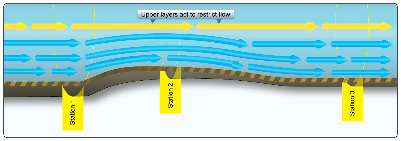
While the amount of total energy within a closed system (the tube) does not change, the form of the energy may be altered. Pressure of flowing air may be compared to energy in that the total pressure of flowing air always remains constant unless energy is added or removed. Fluid flow pressure has two components—static and dynamic pressure. Static pressure is the pressure component measured in the flow but not moving with the flow as pressure is measured. Static pressure is also known as the force per unit area acting on a surface. Dynamic pressure of flow is that component existing as a result of movement of the air. The sum of these two pressures is total pressure. As air flows through the constriction, static pressure decreases as velocity increases. This increases dynamic pressure. Figure 2-7 depicts the bottom half of the constricted area of the tube, which resembles the top half of an airfoil. Even with the top half of the tube removed, the air still accelerates over the curved area because the upper air layers restrict the flow—just as the top half of the constricted tube did. This acceleration causes decreased static pressure above the curved portion and creates a pressure differential caused by the variation of static and dynamic pressures.
Newton’s Third Law of Motion
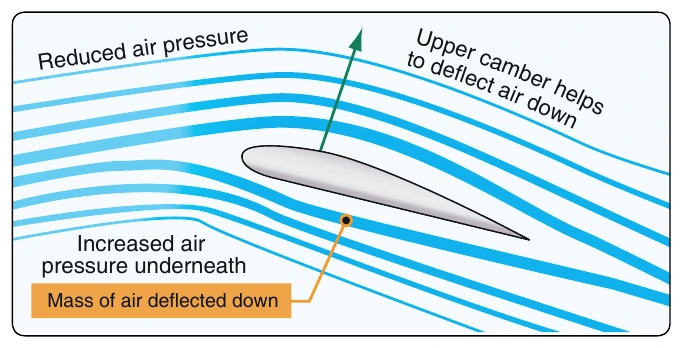
Additional lift is provided by the rotor blade’s lower surface as air striking the underside is deflected downward. According to Newton’s Third Law of Motion, “for every action there is an equal and opposite reaction,” the air that is deflected downward also produces an upward (lifting) reaction.
Since air is much like water, the explanation for this source of lift may be compared to the planing effect of skis on water. The lift that supports the water skis (and the skier) is the force caused by the impact pressure and the deflection of water from the lower surfaces of the skis.
Under most flying conditions, the impact pressure and the deflection of air from the lower surface of the rotor blade provides a comparatively small percentage of the total lift. The majority of lift is the result of decreased pressure above the blade, rather than the increased pressure below it.
Weight
Normally, weight is thought of as being a known, fixed value, such as the weight of the helicopter, fuel, and occupants. To lift the helicopter off the ground vertically, the rotor disk must generate enough lift to overcome or offset the total weight of the helicopter and its occupants. Newton’s First Law states: “Every object in a state of uniform motion tends to remain in that state of motion unless an external force is applied to it.” In this case, the object is the helicopter whether at a hover or on the ground and the external force applied to it is lift, which is accomplished by increasing the pitch angle of the main rotor blades. This action forces the helicopter into a state of motion, without it the helicopter would either remain on the ground or at a hover.
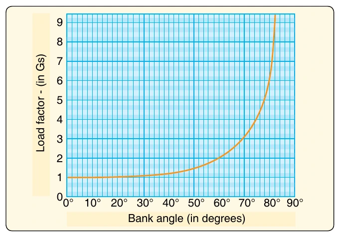
The weight of the helicopter can also be influenced by aerodynamic loads. When you bank a helicopter while maintaining a constant altitude, the “G” load or load factor increases. The load factor is the actual load on the rotor blades at any time, divided by the normal load or gross weight (weight of the helicopter and its contents). Any time a helicopter flies in a constant altitude curved flightpath, the load supported by the rotor blades is greater than the total weight of the helicopter. The tighter the curved flightpath is, the steeper the bank is; the more rapid the flare or pullout from a dive is, the greater the load supported by the rotor. Therefore, the greater the load factor must be. [Figure 2-8]
To overcome this additional load factor, the helicopter must be able to produce more lift. If excess engine power is not available, the helicopter either descends or has to decelerate in order to maintain the same altitude. The load factor and, hence, apparent gross weight increase is relatively small in banks up to 30°. Even so, under the right set of adverse circumstances, such as high-density altitude, turbulent air, high gross weight, and poor pilot technique, sufficient or excess power may not be available to maintain altitude and airspeed. Pilots must take all of these factors into consideration throughout the entire flight from the point of ascending to a hover to landing. Above 30° of bank, the apparent increase in gross weight soars. At 30° of bank, or pitch, the apparent increase is only 16 percent, but at 60°, it is twice the load on the wings and rotor disk. For example, if the weight of the helicopter is 1,600 pounds, the weight supported by the rotor disk in a 30° bank at a constant altitude would be 1,856 pounds (1,600 + 16 percent (or 256)). In a 60° bank, it would be 3,200 pounds; in an 80° bank, it would be almost six times as much, or 8,000 pounds. It is important to note that each rotor blade must support a percentage of the gross weight. In a two-bladed system, each blade of the 1,600-pound helicopter as stated above would have to lift 50 percent or 800 pounds. If this same helicopter had three rotor blades, each blade would have to lift only 33 percent, or 533 pounds. One additional cause of large load factors is rough or turbulent air. The severe vertical gusts produced by turbulence can cause a sudden increase in AOA, resulting in increased rotor blade loads that are resisted by the inertia of the helicopter.