
Chapter 2
Aerodynamics of Flight
Airfoil Terminology and Definitions
- Blade span—the length of the rotor blade from center of rotation to tip of the blade.
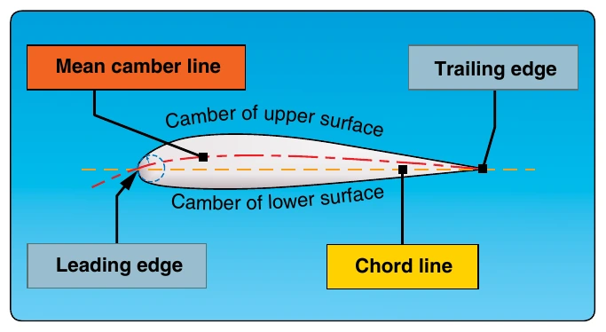
- Chord line—a straight line intersecting leading and trailing edges of the airfoil. [Figure 2-12]
- Chord—the length of the chord line from leading edge to trailing edge; it is the characteristic longitudinal dimension of the airfoil section.
- Mean camber line—a line drawn halfway between the upper and lower surfaces of the airfoil. [Figure 2-12]
The chord line connects the ends of the mean camber line. Camber refers to curvature of the airfoil and may be considered as curvature of the mean camber line. The shape of the mean camber is important for determining aerodynamic characteristics of an airfoil section. Maximum camber (displacement of the mean camber line from the chord line) and its location help to define the shape of the mean camber line. The location of maximum camber and its displacement from the chord line are expressed as fractions or percentages of the basic chord length. By varying the point of maximum camber, the manufacturer can tailor an airfoil for a specific purpose. The profile thickness and thickness distribution are important properties of an airfoil section.
- Leading edge—the front edge of an airfoil. [Figure 2-12]
- Flightpath velocity—the speed and direction of the airfoil passing through the air. For airfoils on an airplane, the flightpath velocity is equal to true airspeed (TAS). For helicopter rotor blades, flightpath velocity is equal to rotational velocity, plus or minus a component of directional airspeed. The rotational velocity of the rotor blade is lowest closer to the hub and increases outward towards the tip of the blade during rotation.
- Relative wind—defined as the airflow relative to an airfoil and is created by movement of an airfoil through the air. This is rotational relative wind for rotary-wing aircraft and is covered in detail later. As an induced airflow may modify flightpath velocity, relative wind experienced by the airfoil may not be exactly opposite its direction of travel.
- Trailing edge—the rearmost edge of an airfoil.
- Induced flow—the downward flow of air through the rotor disk.
- Resultant relative wind—relative wind modified by induced flow.
- AOA—the angle measured between the resultant relative wind and chord line.
- Angle of incidence (AOI)—the angle between the chord line of a blade and rotor hub. It is usually referred to as blade pitch angle. For fixed airfoils, such as vertical fins or elevators, angle of incidence is the angle between the chord line of the airfoil and a selected reference plane of the helicopter.
- Center of pressure—the point along the chord line of an airfoil through which all aerodynamic forces are considered to act. Since pressures vary on the surface of an airfoil, an average location of pressure variation is needed. As the AOA changes, these pressures change, and the center of pressure moves along the chord line.
Airfoil Types
Symmetrical Airfoil
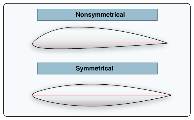
The symmetrical airfoil is distinguished by having identical upper and lower surfaces. [Figure 2-13] The mean camber line and chord line are the same on a symmetrical airfoil, and it produces no lift at zero AOA. Most light helicopters incorporate symmetrical airfoils in the main rotor blades.
Nonsymmetrical Airfoil (Cambered)
The nonsymmetrical airfoil has different upper and lower surfaces, with a greater curvature of the airfoil above the chord line than below. [Figure 2-13] The mean camber line and chord line are different. The nonsymmetrical airfoil design can produce useful lift at zero AOA. A nonsymmetrical design has advantages and disadvantages. The advantages are more lift production at a given AOA than a symmetrical design, an improved lift-to-drag ratio, and better stall characteristics. The disadvantages are center of pressure travel of up to 20 percent of the chord line (creating undesirable torque on the airfoil structure) and greater production costs.
Blade Twist
Because of lift differential due to differing rotational relative wind values along the blade, the blade should be designed with a twist to alleviate internal blade stress and distribute the lifting force more evenly along the blade. Blade twist provides higher pitch angles at the root where velocity is low and lower pitch angles nearer the tip where velocity is higher. This increases the induced air velocity and blade loading near the inboard section of the blade. [Figure 2-14]
Rotor Blade and Hub Definitions
- Hub—on the mast, the attaching point for the root of the blade, and the axis about which the blades rotate. [See Figure 1-7]
- Tip—the farthest outboard section of the rotor blade
- Root—the inner end of the blade and is the point that attaches to the hub
- Twist—the change in blade incidence from the root to the outer blade
The angular position of the main rotor blades (as viewed from above, as they rotate about the vertical axis of the mast) is measured from the helicopter’s longitudinal axis, and usually from its nose. The radial position of a segment of the blade is the distance from the hub as a fraction of the total distance.