
Chapter 2
Aerodynamics of Flight
Each type of helicopter has its own limitations that are based on the aircraft structure, size, and capabilities. Regardless of how much weight one can carry or the engine power that it may have, they are all susceptible to aerodynamic overloading. Unfortunately, if the pilot attempts to push the performance envelope the consequence can be fatal. Aerodynamic forces effect every movement in a helicopter, whether it is increasing the collective or a steep bank angle. Anticipating results from a particular maneuver or adjustment of a flight control is not good piloting technique. Instead pilots need to truly understand the capabilities of the helicopter under any and all circumstances and plan never to exceed the flight envelope for any situation.
Thrust
Thrust, like lift, is generated by the rotation of the main rotor disk. In a helicopter, thrust can be forward, rearward, sideward, or vertical. The resultant lift and thrust determines the direction of movement of the helicopter.
The solidity ratio is the ratio of the total rotor blade area, which is the combined area of all the main rotor blades, to the total rotor disk area. This ratio provides a means to measure the potential for a rotor disk to provide thrust and lift. The mathematical calculations needed to calculate the solidity ratio for each helicopter may not be of importance to most pilots but what should be are the capabilities of the rotor disk to produce and maintain lift. Many helicopter accidents are caused from the rotor disk being overloaded. Simply put, pilots attempt maneuvers that require more lift than the rotor disk can produce or more power than the helicopter’s powerplant can provide. Trying to land with a nose high attitude along with any other unfavorable condition (i.e., high gross weight or wind gusts) is most likely to end in disaster.
The tail rotor also produces thrust. The amount of thrust is variable through the use of the antitorque pedals and is used to control the helicopter’s yaw.
Drag
The force that resists the movement of a helicopter through the air and is produced when lift is developed is called drag. Drag must be overcome by the engine to turn the rotor. Drag always acts parallel to the relative wind. Total drag is composed of three types of drag: profile, induced, and parasite.
Profile Drag
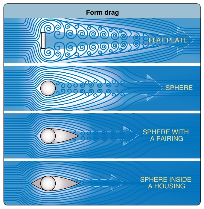
Profile drag develops from the frictional resistance of the blades passing through the air. It does not change significantly with the airfoil’s AOA but increases moderately when airspeed increases. Profile drag is composed of form drag and skin friction. Form drag results from the turbulent wake caused by the separation of airflow from the surface of a structure. The amount of drag is related to both the size and shape of the structure that protrudes into the relative wind. [Figure 2-9] Skin friction is caused by surface roughness. Even though the surface appears smooth, it may be quite rough when viewed under a microscope. A thin layer of air clings to the rough surface and creates small eddies that contribute to drag.
Induced Drag
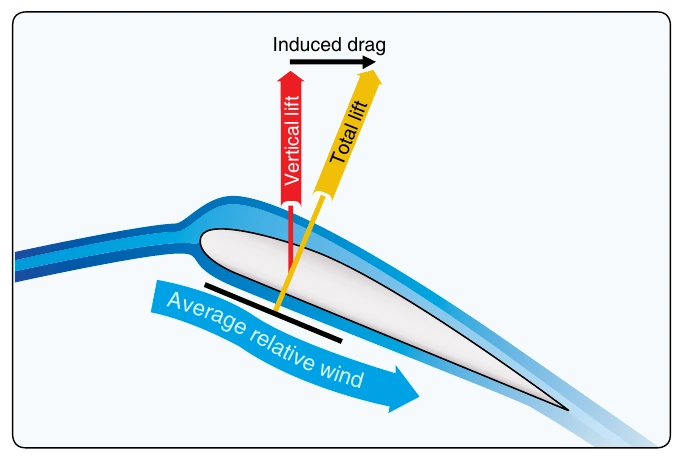
Induced drag is generated by the airflow circulation around the rotor blade as it creates lift. The high-pressure area beneath the blade joins the low-pressure area above the blade at the trailing edge and at the rotor tips. This causes a spiral, or vortex, which trails behind each blade whenever lift is being produced. These vortices deflect the airstream downward in the vicinity of the blade, creating an increase in downwash. Therefore, the blade operates in an average relative wind that is inclined downward and rearward near the blade. Because the lift produced by the blade is perpendicular to the relative wind, the lift is inclined aft by the same amount. The component of lift that is acting in a rearward direction is induced drag. [Figure 2-10]
As the air pressure differential increases with an increase in AOA, stronger vortices form, and induced drag increases. Since the blade’s AOA is usually lower at higher airspeeds, and higher at low speeds, induced drag decreases as airspeed increases and increases as airspeed decreases. Induced drag is the major cause of drag at lower airspeeds.
Parasite Drag
Parasite drag is present any time the helicopter is moving through the air. This type of drag increases with airspeed. Non-lifting components of the helicopter, such as the cabin, rotor mast, tail, and landing gear, contribute to parasite drag. Any loss of momentum by the airstream, due to such things as openings for engine cooling, creates additional parasite drag. Because of its rapid increase with increasing airspeed, parasite drag is the major cause of drag at higher airspeeds. Parasite drag varies with the square of the velocity; therefore, doubling the airspeed increases the parasite drag four times.
Total Drag
Total drag for a helicopter is the sum of all three drag forces. [Figure 2-11] As airspeed increases, parasite drag increases, while induced drag decreases. Profile drag remains relatively constant throughout the speed range with some increase at higher airspeeds. Combining all drag forces results in a total drag curve. The low point on the total drag curve shows the airspeed at which drag is minimized. This is the point where the lift-to-drag ratio is greatest and is referred to as L/DMAX. At this speed, the total lift capacity of the helicopter, when compared to the total drag of the helicopter, is most favorable. This is an important factor in helicopter performance.
Airfoil
Helicopters are able to fly due to aerodynamic forces produced when air passes around the airfoil. An airfoil is any surface producing more lift than drag when passing through the air at a suitable angle. Airfoils are most often associated with production of lift. Airfoils are also used for stability (fin), control (elevator), and thrust or propulsion (propeller or rotor). Certain airfoils, such as rotor blades, combine some of these functions. The main and tail rotor blades of the helicopter are airfoils, and air is forced to pass around the blades by mechanically powered rotation. In some conditions, parts of the fuselage, such as the vertical and horizontal stabilizers, can become airfoils. Airfoils are carefully structured to accommodate a specific set of flight characteristics.