
Chapter 1
The National Airspace System
National Security Areas (NSAs) consist of airspace with defined vertical and lateral dimensions established at locations where there is a requirement for increased security and safety of ground facilities. Flight in NSAs may be temporarily prohibited by regulation under the provisions of Title 14 of the Code of Federal Regulations (14 CFR) part 99 and prohibitions will be disseminated via NOTAM.
Federal Airways
The primary means for routing aircraft operating under IFR is the Federal Airways System. Each Federal airway is based on a centerline that extends from one navigational aid (NAVAID)/waypoint/fix/intersection to another NAVAID/waypoint/fix/intersection specified for that airway. A Federal airway includes the airspace within parallel boundary lines 4 NM to each side of the centerline. As in all instrument flight, courses are magnetic, and distances are in NM. The airspace of a Federal airway has a floor of 1,200 feet AGL, unless otherwise specified. A Federal airway does not include the airspace of a prohibited area.
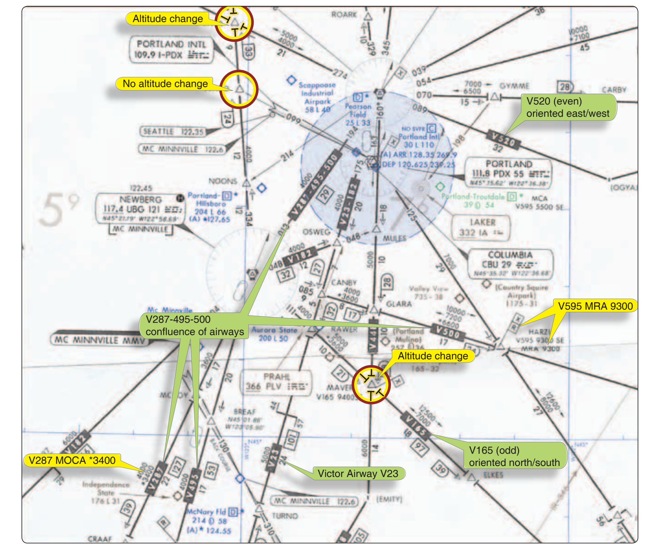
Victor airways include the airspace extending from 1,200 feet AGL up to, but not including 18,000 feet MSL. The airways are designated on sectional and IFR low altitude en route charts with the letter “V” followed by a number (e.g., “V23”). Typically, Victor airways are given odd numbers when oriented north/south and even numbers when oriented east/west. If more than one airway coincides on a route segment, the numbers are listed serially (e.g., “V287-495- 500”). [Figure 1-2] Jet routes exist only in Class A airspace, from 18,000 feet MSL to FL 450, and are depicted on high-altitude en route charts. The letter “J” precedes a number to label the airway (e.g., J12).
Area navigation (RNAV) routes have been established in both the low-altitude and the high-altitude structures in recent years and are depicted on the en route low and high chart series. High altitude RNAV routes are identified with a “Q” prefix (except the Q-routes in the Gulf of Mexico) and low altitude RNAV routes are identified with a “T” prefix. RNAV routes and data are depicted in aeronautical blue.
In addition to the published routes, a random RNAV route may be flown under IFR if it is approved by ATC. Random RNAV routes are direct routes, based on RNAV capability, between waypoints defined in terms of latitude/longitude coordinates, degree-distance fixes, or offsets from established routes/airways at a specified distance and direction.
Radar monitoring by ATC is required on all random RNAV routes. These routes can only be approved in a radar environment. Factors that are considered by ATC in approving random RNAV routes include the capability to provide radar monitoring and compatibility with traffic volume and flow. ATC will radar monitor each flight; however, navigation on the random RNAV route is the responsibility of the pilot.
Other Routing
Preferred IFR routes have been established between major terminals to guide pilots in planning their routes of flight, minimizing route changes, and aiding in the orderly management of air traffic on Federal airways. Low and high altitude preferred routes are listed in the Airport/Facility Directory (A/FD). To use a preferred route, reference the departure and arrival airports; if a routing exists for your flight, then airway instructions are listed.
Tower En Route Control (TEC) is an ATC program that uses overlapping approach control radar services to provide IFR clearances. By using TEC, a pilot is routed by airport control towers. Some advantages include abbreviated filing procedures and reduced traffic separation requirements. TEC is dependent upon the ATC’s workload, and the procedure varies among locales.
The latest version of Advisory Circular (AC) 90-91, North American Route Program (NRP), provides guidance to users of the NAS for participation in the NRP. All flights operating at or above FL 290 within the conterminous United States and Canada are eligible to participate in the NRP, the primary purpose of which is to allow operators to plan minimum time/cost routes that may be off the prescribed route structure. NRP aircraft are not subject to route-limiting restrictions (e.g., published preferred IFR routes) beyond a 200 NM radius of their point of departure or destination.
IFR En Route Charts
The objective of IFR en route flight is to navigate within the lateral limits of a designated airway at an altitude consistent with the ATC clearance. Your ability to fly instruments safely and competently in the system is greatly enhanced by understanding the vast array of data available to the pilot on instrument charts. AeroNav Products maintains and produces the charts for the U.S. Government.
En route high-altitude charts provide aeronautical information for en route instrument navigation at or above 18,000 feet MSL. Information includes the portrayal of Jet and RNAV routes, identification and frequencies of radio aids, selected airports, distances, time zones, special use airspace, and related information. Established jet routes from 18,000 feet MSL to FL 450 use NAVAIDs not more than 260 NM apart. The charts are revised every 56 days.
To effectively depart from one airport and navigate en route under instrument conditions, a pilot needs the appropriate IFR en route low-altitude chart(s). The IFR low altitude en route chart is the instrument equivalent of the sectional chart. When folded, the cover of the AeroNav Products en route chart displays an index map of the United States showing the coverage areas. Cities near congested airspace are shown in black type and their associated area chart is listed in the box in the lower left-hand corner of the map coverage box. Also noted is an explanation of the off-route obstruction clearance altitude (OROCA). The effective date of the chart is printed on the other side of the folded chart. Information concerning MTRs is also included on the chart cover. The en route charts are revised every 56 days.
When the AeroNav Products en route chart is unfolded, the legend is displayed and provides information concerning airports, NAVAIDs, communications, air traffic services, and airspace.
Airport Information
Airport information is provided in the legend, and the symbols used for the airport name, elevation, and runway length are similar to the sectional chart presentation. Associated city names are shown for public airports only. FAA identifiers are shown for all airports. ICAO identifiers are also shown for airports outside of the contiguous United States. Instrument approaches can be found at airports with blue or green symbols, while the brown airport symbol denotes airports that do not have instrument approaches. Stars are used to indicate the part-time nature of tower operations, Automatic Terminal Information Service (ATIS) frequencies, part-time or on request lighting facilities, and part-time airspace classifications. A box after an airport name with a “C” or “D” inside [boxed “C” and boxed “D” airspace-class symbols] indicates Class C and D airspace, respectively, per Figure 1-3.