
Chapter 1
The National Airspace System
Today’s computerized system of ATC has greatly reduced the need for holding en route. However, published holding patterns are still found on charts at junctures where ATC has deemed it necessary to enable traffic flow. When a holding pattern is charted [holding-pattern symbol], the controller may provide the holding direction and the statement “as published.” [Figure 1-4]
Boundaries separating the jurisdiction of Air Route Traffic Control Centers (ARTCC) are depicted on charts with blue serrations [serrated boundary-line symbol]. The name of the controlling facility is printed on the corresponding side of the division line. ARTCC remote sites are depicted as blue serrated boxes and contain the center name, sector name, and the sector frequency. [Figure 1-4]
Weather Information and Communication Features
En route NAVAIDs also provide weather information and serve communication functions. When a NAVAID is shown as a shadowed box [Harrison HRO shadowed NAVAID/AFSS box], an automated flight service station (AFSS) of the same name is directly associated with the facility. If an AFSS is located without an associated NAVAID, the shadowed box is smaller and contains only the name and identifier. The AFSS frequencies are provided above the box. (Frequencies 122.2 and 255.4, and emergency frequencies 121.5 and 243.0 are not listed.) [El Dorado ELD standalone AFSS box]
A Remote Communications Outlet (RCO) associated with a NAVAID is designated by a thin-lined box with the controlling AFSS frequency above the box and the name under the box. Without an associated facility, the thin-lined RCO box contains the AFSS name and remote frequency [Pine Bluff PBF NAVAID/RCO box; Jonesboro 122.55 standalone RCO box].
Automated Surface Observing Station (ASOS), Automated Weather Observing Station (AWOS), Hazardous Inflight Weather Advisory Service (HIWAS), and Transcribed Weather Broadcast (TWEB) are continuously transmitted over selected NAVAIDs and depicted in the NAVAID box. ASOS/AWOS are depicted by a white “A”, HIWAS by a “H” and TWEB broadcasts by a “T” in a solid black circle in the upper right or left corner [example Pine Bluff PBF box marked H/T].
New Technologies
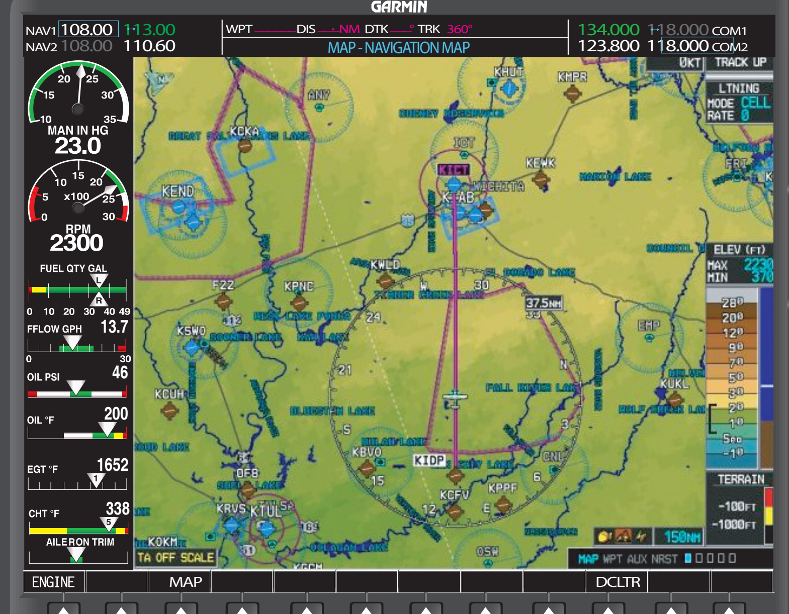
Technological advances have made multifunction displays and moving maps more common in newer aircraft. Even older aircraft are being retrofitted to include “glass” in the flight deck. [Figure 1-6] Moving maps improve pilot situational awareness (SA) by providing a picture of aircraft location in relation to NAVAIDS, waypoints, airspace, terrain, and hazardous weather. GPS systems can be certified for terminal area and en route use as well as approach guidance.
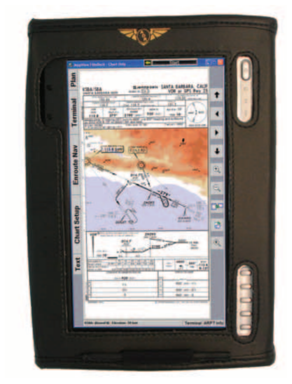
Additional breakthroughs in display technology are the new electronic chart systems or electronic flight bags that facilitate the use of electronic documents in the general aviation flight deck. [Figure 1-7] An electronic chart or flight bag is a self-powered electronic library that stores and displays en route charts and other essential documents on a screen. These electronic devices can store the digitized United States terminal procedures, en route charts, the complete A/FD, in addition to 14 CFR and the AIM. Full touch-screen based computers allow pilots to view airport approach and area charts electronically while flying. With FAA approval, an operator may replace paper charts as well as other paper materials including minimum equipment lists (MELs), standard operating procedures (SOPs), standard instrument departures (SIDs), standard terminal arrival routes (STARs), checklists, and flight deck manuals. As with paper flight publications, the electronic database needs to be current to provide accurate information regarding NAVAIDS, waypoints, and terminal procedures. Databases are updated every 28 days and are available from various commercial vendors. Pilots should be familiar with equipment operation, capabilities, and limitations prior to use.
Terminal Procedures Publications
While the en route charts provide the information necessary to safely transit broad regions of airspace, the United States Terminal Procedures Publication (TPP) enables pilots to guide their aircraft in the airport area. Whether departing or arriving, these procedures exist to make the controllers’ and pilots’ jobs safer and more efficient. Available in booklets by region (published by AeroNav Products), the TPP includes approach procedures, STARs, Departure Procedures (DPs), and airport diagrams.
Departure Procedures
There are two types of DPs: Obstacle Departure Procedures (ODP) and SIDs. [Figure 1-8] Both types of DPs provide obstacle clearance protection to aircraft in instrument meteorological conditions (IMC), while reducing communications and departure delays. DPs are published in text and/or charted graphic form. Regardless of the format, all DPs provide a way to depart the airport and transition to the en route structure safely. When possible, pilots are strongly encouraged to file and fly a DP at night, during marginal visual meteorological conditions (VMC) and IMC.
All DPs provide obstacle clearance provided the aircraft crosses the end of the runway at least 35 feet AGL; climbs to 400 feet above airport elevation before turning; and climbs at least 200 feet per nautical mile (FPNM), unless a higher climb gradient is specified to the assigned altitude. ATC may vector an aircraft off a previously assigned DP; however, the 200 FPNM or the FPNM specified in the DP is required.
Textual ODPs are listed by city and airport in the IFR Take- Off Minimums and DPs section of the TPP. SIDs are depicted in the TPP following the approach procedures for the airport.
Standard Terminal Arrival Routes
STARs depict prescribed routes to transition the instrument pilot from the en route structure to a fix in the terminal area from which an instrument approach can be conducted. If a pilot does not have the appropriate STAR, write “No STAR” in the flight plan. However, if the controller is busy, the pilot might be cleared along the same route and, if necessary, the controller has the pilot copy the entire text of the procedure.
STARs are listed alphabetically at the beginning of the AeroNav Products booklet. Figure 1-9 shows an example of a STAR, and the legend for STARs and DPs printed in AeroNav Products booklets.