
Chapter 1
The National Airspace System
The minimum en route altitude (MEA) ensures a navigation signal strong enough for adequate reception by the aircraft navigation (NAV) receiver and obstacle clearance along the airway. Communication is not necessarily guaranteed with MEA compliance. The obstacle clearance, within the limits of the airway, is typically 1,000 feet in non-mountainous areas and 2,000 feet in designated mountainous areas. MEAs can be authorized with breaks in the signal coverage; if this is the case, the AeroNav Products en route chart notes “MEA GAP” parallel to the affected airway. MEAs are usually bidirectional; however, they can be single-directional. Arrows are used to indicate the direction to which the MEA applies.
The minimum obstruction clearance altitude (MOCA), as the name suggests, provides the same obstruction clearance as an MEA; however, the NAV signal reception is ensured only within 22 NM of the closest NAVAID defining the route. The MOCA is listed below the MEA and indicated on AeroNav Products charts by a leading asterisk (e.g., “*3400”—see Figure 1-2, V287 at bottom left).
The minimum reception altitude (MRA) identifies the lowest altitude at which an intersection can be determined from an off-course NAVAID. If the reception is line-of-sight based, signal coverage only extends to the MRA or above. However, if the aircraft is equipped with distance measuring equipment (DME) and the chart indicates the intersection can be identified with such equipment, the pilot could define the fix without attaining the MRA. On AeroNav Products charts, the MRA is indicated by the symbol [flag-shaped “R” minimum-reception-altitude symbol] and the altitude preceded by “MRA” (e.g., “MRA 9300”). [Figure 1-2]
The minimum crossing altitude (MCA) is charted when a higher MEA route segment is approached. The MCA is usually indicated when a pilot is approaching steeply rising terrain and obstacle clearance and/or signal reception is compromised. In this case, the pilot is required to initiate a climb so the MCA is reached by the time the intersection is crossed. On AeroNav Products charts, the MCA is indicated by the symbol [flag-shaped “X” minimum-crossing-altitude symbol] and the Victor airway number, altitude, and the direction to which it applies (e.g. “V24 8000 SE”).
The maximum authorized altitude (MAA) is the highest altitude at which the airway can be flown with assurance of receiving adequate navigation signals. Chart depictions appear as “MAA-15000.”
When an MEA, MOCA, and/or MAA change on a segment other than at a NAVAID, a sideways “T” [sideways-“T” airway-altitude-change symbol] is depicted on the chart. If there is an airway break without the symbol, one can assume the altitudes have not changed (see the upper left area of Figure 1-2). When a change of MEA to a higher MEA is required, the climb may commence at the break, ensuring obstacle clearance. [Figure 1-4]
Navigation Features
Types of NAVAIDs
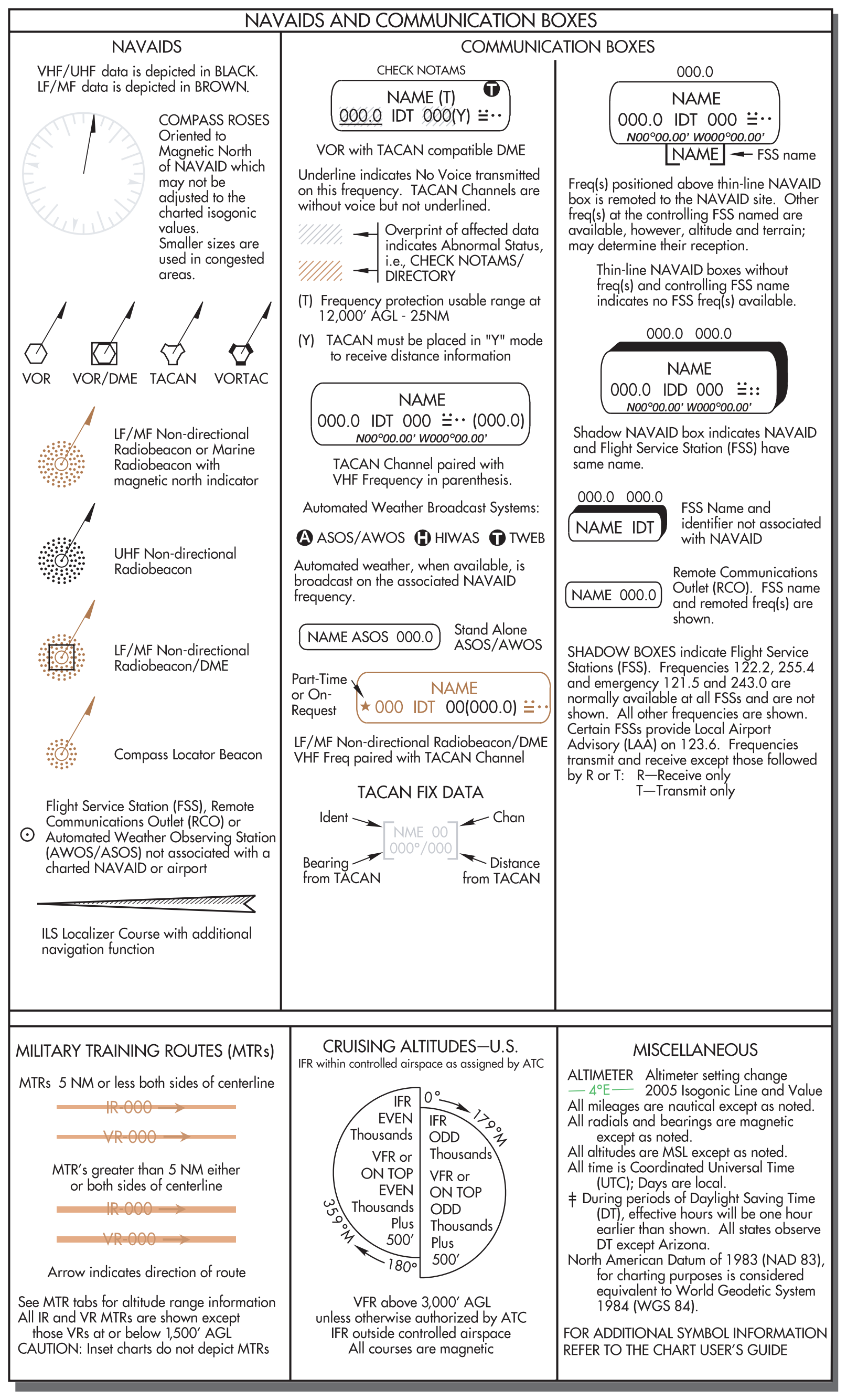
Very high frequency omnidirectional ranges (VORs) are the principal NAVAIDs that support the Victor and Jet airways. Many other navigation tools are also available to the pilot. For example, nondirectional beacons (NDBs) can broadcast signals accurate enough to provide stand-alone approaches, and DME allows the pilot to pinpoint a reporting point on the airway. Though primarily navigation tools, these NAVAIDs can also transmit voice broadcasts.
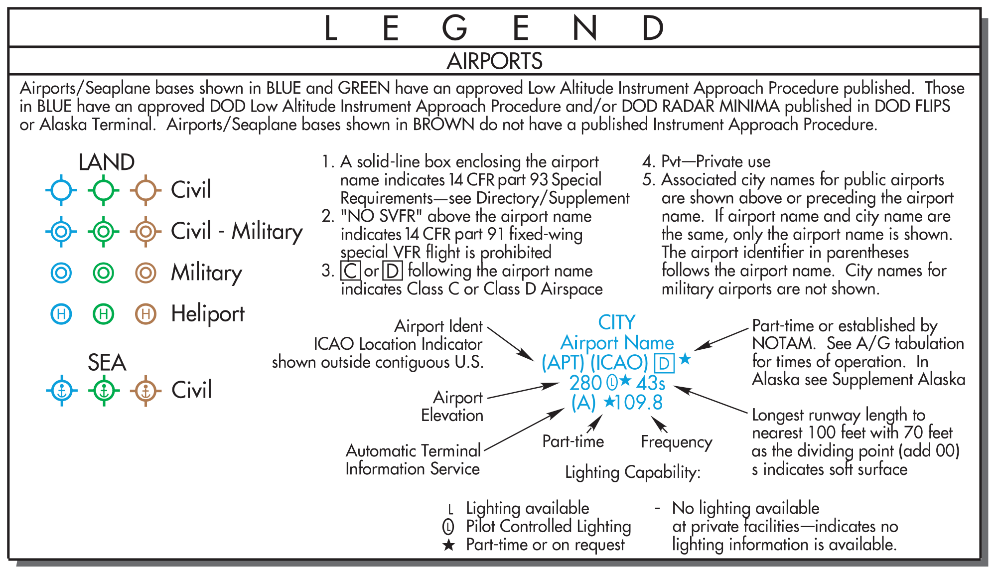
Tactical air navigation (TACAN) channels are represented as the two- or three-digit numbers following the three-letter identifier in the NAVAID boxes. The AeroNav Products terminal procedures provide a frequency-pairing table for the TACAN-only sites. On AeroNav Products charts, very-high frequencies and ultra-high frequencies (VHF/UHF) NAVAIDs (e.g., VORs) are depicted in black, while low frequencies and medium frequencies (LF/MF) are depicted as brown. [Figure 1-5]
Identifying Intersections
Intersections along the airway route are established by a variety of NAVAIDs. An open triangle [open-triangle noncompulsory-reporting-point symbol] indicates the location of an ATC reporting point at an intersection. If the triangle is solid [solid-triangle compulsory-reporting-point symbol], a report is compulsory. [Figure 1-4] NDBs, localizers, and off-route VORs are used to establish intersections. NDBs are sometimes collocated with intersections, in which case passage of the NDB would mark the intersection. A bearing to an off-route NDB also can provide intersection identification. A localizer course used to identify an intersection is depicted by a feathered arrowhead symbol on the en route chart [front-course localizer feathered-arrow symbol]. If feathered markings appear on the left-hand side of the arrowhead [back-course localizer feathered-arrow symbol], a back course (BC) signal is transmitted. On AeroNav Products en route charts, the localizer symbol is only depicted to identify an intersection.
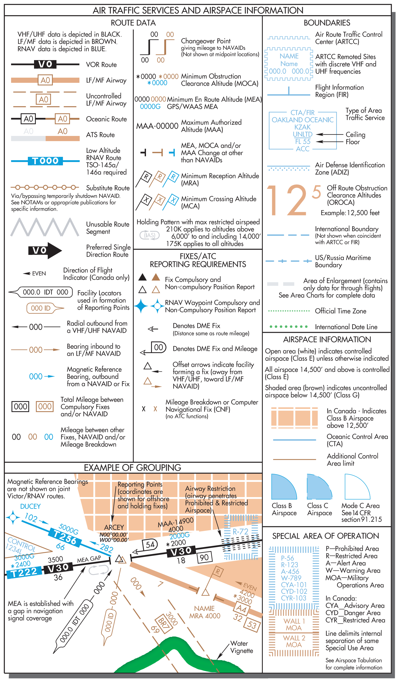
Off-route VORs remain the most common means of identifying intersections when traveling on an airway. Arrows depicted next to the intersection indicate the NAVAID to be used for identification. Another means of identifying an intersection is with the use of DME. A hollow arrowhead indicates DME is authorized for intersection identification. If the DME mileage at the intersection is a cumulative distance of route segments, the mileage is totaled and indicated by a D-shaped symbol with a mileage number inside. [Figure 1-4] Approved IFR global positioning system (GPS) units can also be used to report intersections.
Other Route Information
DME and GPS provide valuable route information concerning such factors as mileage, position, and ground speed. Even without this equipment, information is provided on the charts for making the necessary calculations using time and distance. The en route chart depicts point-to-point distances on the airway system. Distances from VOR to VOR are charted with a number inside of a box [boxed three-digit airway mileage, e.g. 000]. To differentiate distances when two airways coincide, the word “TO” with the three-letter VOR identifier appear to the left of the distance boxes [TO PDX with boxed 97].
VOR changeover points (COPs) are depicted on the charts by this symbol [VOR changeover-point symbol; mileage shown above]. The numbers indicate the distance at which to change the VOR frequency. The frequency change might be required due to signal reception or conflicting frequencies. If a COP does not appear on an airway, the frequency should be changed midway between the facilities. A COP at an intersection may indicate a course change.
Occasionally an “x” appears at a separated segment of an airway that is not an intersection. The “x” is a mileage breakdown or computer navigation fix and may indicate a course change.